 |
|
|
|
Site Navigation
Projects & Information
»General Information»Wind turbine Projects »The F&P Smartdrive »Electronic projects »Microcontroller projects »Miscellaneous Kits & Parts
»Basicly Natural Pty Ltd»PVC & Aluminium blades »Scale model farm windmills »Price Watch Discussion Forums
Handy Links
»Wind»Solar »Electric Vehicles »Electronics »Micro Controllers »General Interrest About TheBackShed Getting Started Privacy Policy |
Easy to build encapsulated load resistors.
|
||||||||||||||

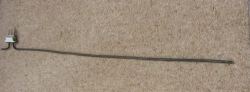
So it was out to the shed to test the idea. First find an element, the longer the overall length the better. This one was rated at 2000 watts (2Kw) at 240 volts. Or 8.3 amp. There is a steel conductor inserted in each end that the terminals attach to. The conductor goes approx 75mm (3”) into the element . It can be easy checked with a magnet where it stops, as the element itself is non magnetic. The section with the steel conductor in it is of no use. Measure the overall lineal length of the element between the two steel conductors each end. (use a piece of string) The element above gave me 1100mm of element between the conductors. It is better to calculate the amps per resistor lower than required, as the resistance can be lowered later to increase the amps but cannot be done vice versa. |
 |
If we have an element rated at 2400 watts for 240 volts, and wish to use it with 24 volts then we could cut it into 10 sections and have 10 x 240 watt resistors. I would recommend that the resistors be only made to half their rated wattage to keep the heat per resistor lower and use 2 in parallel to gain the same wattage. For this reason we would cut the element into 5 sections only, and get a total of 1200 watts with 5 resistors in parallel (5 amp per resistor) Under full rated load (10 amp) they will glow red as they would normally if used in your oven. For a element of 2000 watts at 240 volts, with a total length of 1100mm
You want 4 amps at 29 volts = 116 watts.
For different wattage and length elements, substitute actual values in the above formulae. |
|
Next is to cut the element each end, where the steel conductor stops. This is easy done with a hacksaw and a cut made “around” the outer casing for about half the circumference, and with a gentle back and forth bending to snap the outer in half. Gently pull some of the nichrome wire out of the mineral lining by about 20mm. Cut the nichrome wire so 10mm is protruding out of the element both sides. Gently straighten out the bends in the element so it is one straight length. This is easy to do by hand, then lastly, tap it straight with a rubber mallet.
|
 |
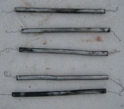
Measure and mark the element into the calculated resistor lengths required. Cut element into sections with hacksaw as previous. Note keep the nichrome wire short as it gets caught in everything when working with it and can/will be stretched out longer later. This gave me 5 resistors around 220mm long. The resistors were buffed on a wire wheel as It is intended to silver solder onto them later. At this point it is up to you, how you choose to mount them. Here is two simple examples. |
 |
 |
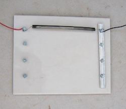 Holes drilled in a ceramic floor tile for 3/16 bolts |
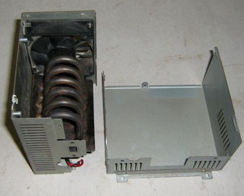
This looked a little boring and I decided to take it further to show what can be done and how easy it is to do. The next intension was to mount the resistors in a old atx psu casing. The fan was to remain, so space is tight.
|
|