 |
|
|
|
Site Navigation
Projects & Information
»General Information»Wind turbine Projects »The F&P Smartdrive »Electronic projects »Microcontroller projects »Miscellaneous Kits & Parts
»Basicly Natural Pty Ltd»PVC & Aluminium blades »Scale model farm windmills »Price Watch Discussion Forums
Handy Links
»Wind»Solar »Electric Vehicles »Electronics »Micro Controllers »General Interrest About TheBackShed Getting Started Privacy Policy |
Adding a expanded scale volt meter to my battery charger. I have a 12v batter charger I put together many years ago from bits and pieces found in the junk box. Its been a good little light duty charger, but was lacking any form of battery monitoring, so I decided to give it an upgrade with a expanded scale volt meter and amp meter.
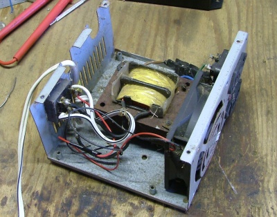
Its not pretty. The transformer and thermal cutout switch were saved from a dropped el-cheapo battery charger, the case is a old PC power supply with fan, and I added a bridge rectifier. Now I need to find a couple of meters.
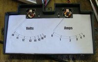
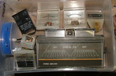
I had collected a few meters from old stereos I junked over the years, never throw anything away I say. The meter movements in these meters are not the best, built to a price and not good choice if you want to make accurate measurements, but for a old clunker battery charger, they will be fine.
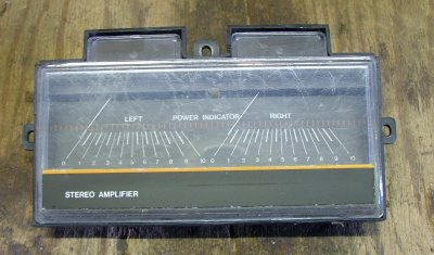
This is the meter I chose for my battery charger. Its has dual movements, so I can use it to measure both volts and amps. Now where is that expanded volt meter circuit? Searching the internet I found several circuits for expanded scale meters, but most of them were over engineered with 1 or more IC's and a handful of components. I wasn't after 1% accuracy, and I didn't care if there was a little temperature drift, I just wanted something to give me a "close enough" reading. I found 2 circuits that I could work with. |
||
|
The simplest circuit.
One problem with this simple circuit is finding a suitable zener diode that matches the minimum voltage you want for your meter. You can connect zener's in series to get odd voltages, eg a 5 volt zener and a 6 volt zener in series will give a 11 volt minimum voltage on the meter. The other problem with this circuit is temperature drift. The zener voltage will change slightly with changes in temperature, in the order of less than 0.05% per degree Centigrade. Its not much, don't worry about it. On the last page of this article I've put together a list of common zener diode and their temperature coefficient, so if you do want less temperature drift, choose the zener's with the lowest temperature coefficient value.
A better circuit.
This circuit uses a wheatsone bridge to give an expanded scale volt meter that can be adjusted to measure any voltage range above the zener voltage. If you use a zener below 10 volts, the meter can be adjusted to read any range above 10 volts, for example, 12 to 15 volts, 22 to 28 volts, 45 to 55 volts, etc. The adjustment of the trimpots can be a little tricky, both VR1 and VR2 can affect each other, so it will take a little longer to get the meter reading right than the circuit above. VR1 sets the meters upper voltage, and VR2 sets the lower limit, and you will need to go back and forth between the trimpots several times to get the adjustment spot on. A couple of things to note about this circuit. First up, its still susceptible to temperature drift. Secondly, you should operate the meter near its adjusted range to protect the meter from excessive current. See, when the input voltage is below the meters minimum voltage, the meter will go into the negative, so if you feed 12v into a meter calibrated for 22 to 28 volts, the meter will be driven hard negative, pegged against its pointer stop. Zener Noise.
More advanced circuit. If you want more accuracy, and reduce temperature drift, you should look at a circuit using a better voltage reference. The following links will get you going....
What about the current?
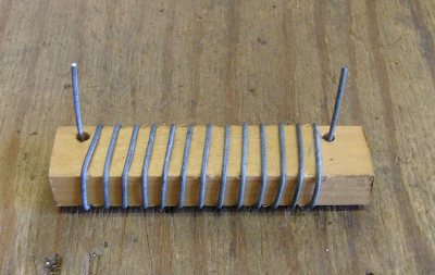
To make the shunt resistor, I used a 400mm long length of 1mm zinc coated steel wire. Steel wire is best, it has a higher resistance than copper, just what we need in a resistor. Using croc clips, I connected the length of steel wire ( R1 ) in series with a dump load and a variable power supply. With VR1 set to to the middle of its range, I cranked up the power supply until I had 2 amps flowing. I then slid the croc clip down the wire until the meter was deflected by half. This gave me the length of wire for my shunt resistor. Trimpot VR1 can be used to make the final adjustment once the shunt resistor if made. The steel wire was wound around a piece of timber. The timber length has a hole in its end for mounting upright.
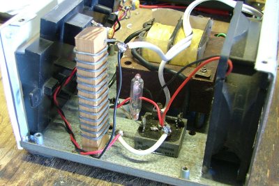
Here's the shunt resistor fitted in place. The small glass tube to the right of the shunt resistor is the thermal cut out.
|
|||
 This is the simplest circuit, and the one I ended up using for my battery charger. The zener diode ZD1 is chosen to suit the minimum meter voltage you want to display. I had a 10 volt zener handy, so 10 volts was going to be my minimum voltage. Resistor R1 is chosen to supply a current of a couple milliamps through the zener diode to make sure its regulating properly. The variable resistor VR1 is the meter scale current adjustment. I used a variable power supply set at 13 volts and adjusted VR1 so the meter was about mid scale. Easy.
 But what if you don't have a zener('s) to give you the minimum meter voltage you wanted?
  Zener Diodes can create small amounts of electrical noise, and this can affect the meter movement if its very sensitive, or if you are using digital meters instead of analogue meters. So its a good idea to add a 10M resistor and 0.01uF capacitor across the zener diode as shown here. These components will filter out any noise before it can affect the meter or any other nearby sensitive circuit. If your still experience erratic behaviour, try a 0.1uF cap in stead of the 0.01uF cap. Thanks to
  To measure the charging current I opted to use a simple shunt resistor. The charger was only good for 5 amps max, so I could use a home made shunt resistor made from some steel wire. The charger is fan cooled, so I didn't need to worry about heat generated by the shunt resistor. The circuit is fairly simple.