| Windmill Kit, no longer supplied.. |
|
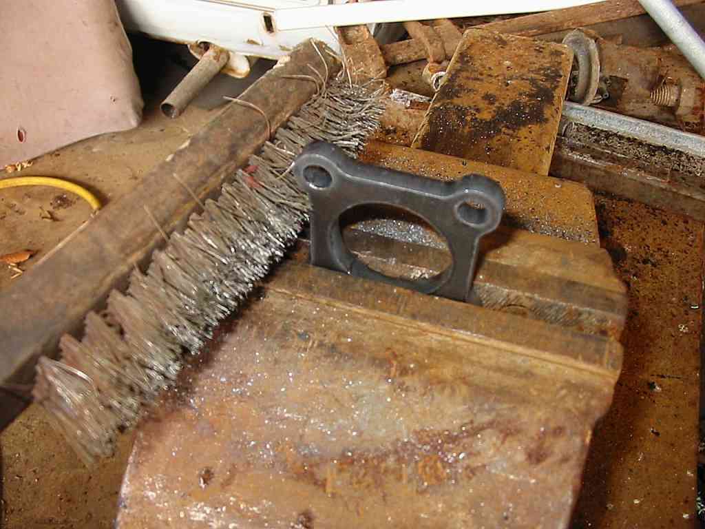
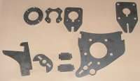
Remove any burrs and rust from steelwork.
We use a laser to cut the steel in the windmill kit.
Lasercutting leaves a loose flaky metal layer on the
cut edge, so use a wire brush to remove.

|
 |
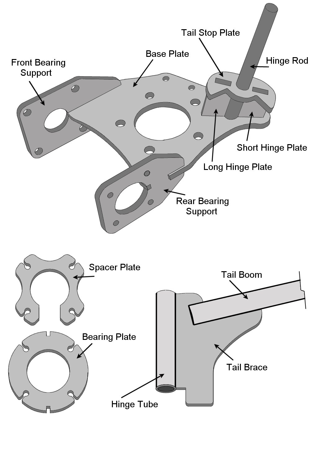
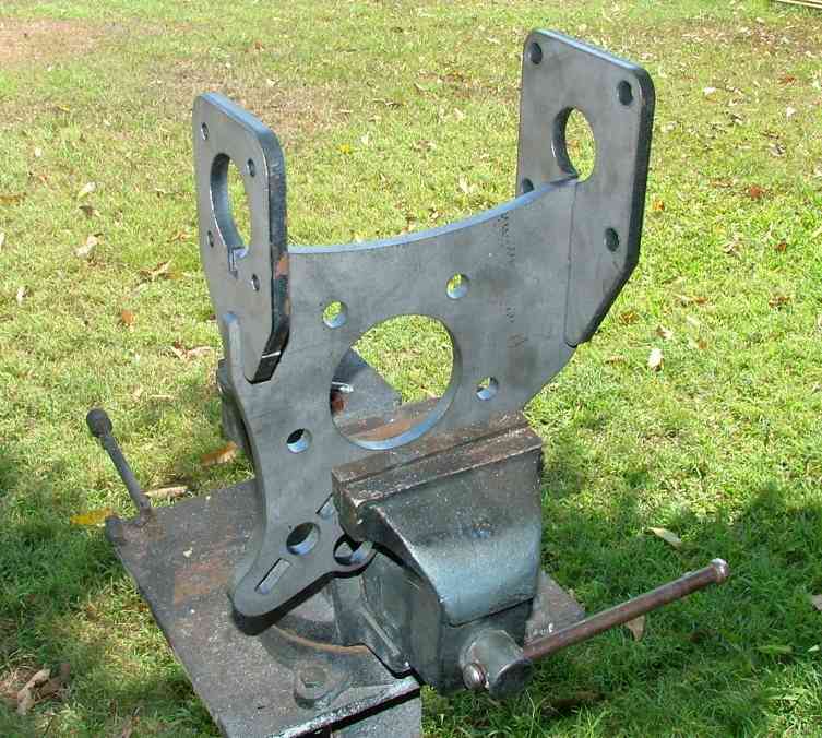
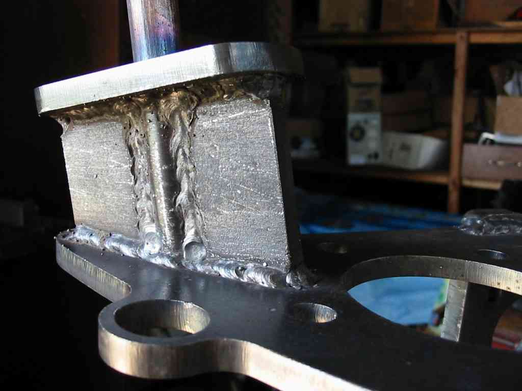
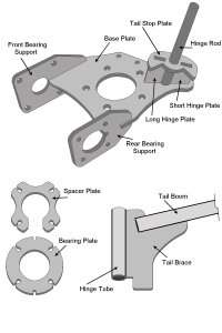
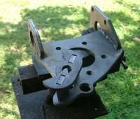
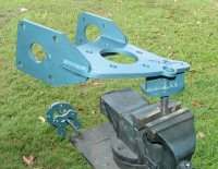
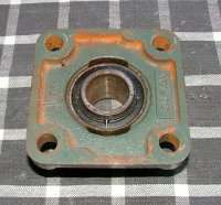
Using a g-clamp, clamp the bearing plate,
front and rear bearing plates as shown, and weld together.
The design of the parts makes it next to impossible
to miss-align, but check all is square before welding.
 
Remember you can click on all the images
to see full size.
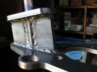
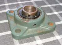
Fully weld all corners. There may be
some buckling from the heat of welding. If so use a
vice and shifter/hammer to make the assembly square.
The rear bearing plate is the most critical. The front
bearing plate holds a floating bearing and housing,
which will self adjust to any imperfections and therefore
does not need to be square. |
 |
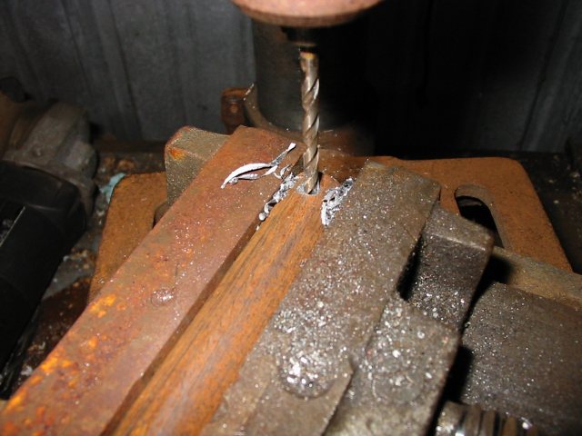
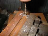
Drill a 4mm hole through the 16mm dia
rod, approx 10mm from one end, This is the split pin
hole to keep the tail in place.
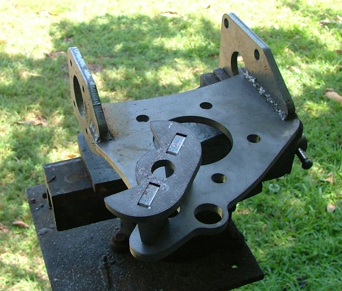
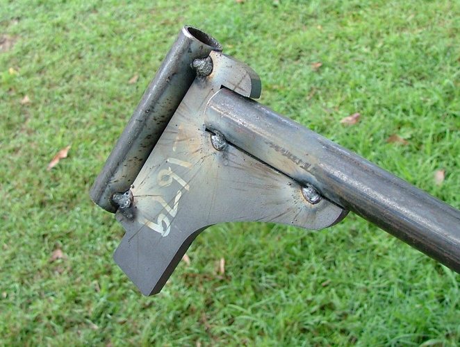
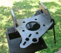
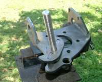
Next clamp and weld the tail axle assembly
to the bearing plate as shown.
You now have a finished bearing plate.

|
|
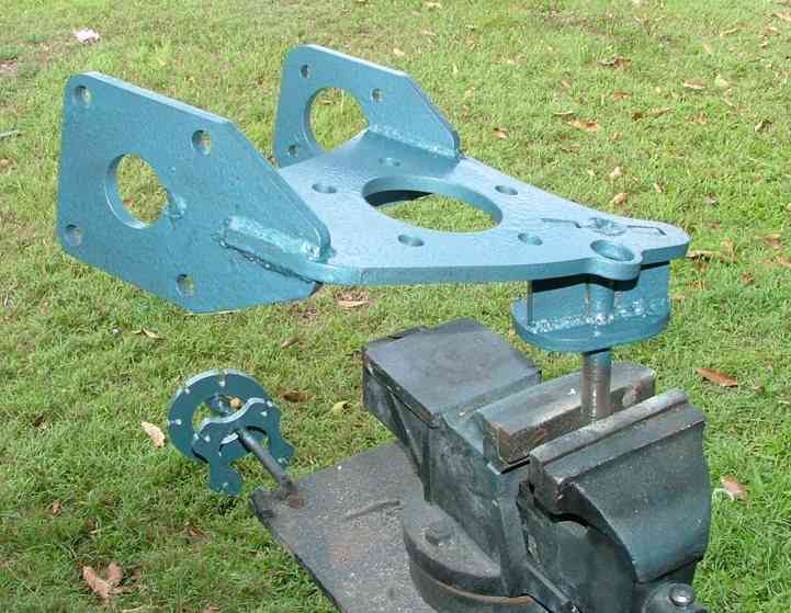
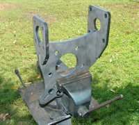
| The platform
can now be painted. Be sure to remove any welding slag
or spikes first with a file/wire brush. I recommend a
good quality metal paint such as KillRust. |
 |
Weld the 100mm and 1000mm long pipes
to the tail bracket as shown. The windmill kit may be
supplied with galvanised pipe, when welding galvanised
pipe you should always grind the gal coating back to
steel and only weld in a well ventilated area as the
fumes are toxic. I recommend some sort of breathing
air filtration.
Note. The 1000mm long pipe is NOT supplied
with the windmill kit. The cost of transport for this
length of tube far outweighed the actual cost of the
pipe itself. You should be able to pick up a length
of pipe for less than $10.
Some pipe has an internal seam that
may need filling/drilling to allow the pipe to slide
over the 16mm rod. Once in place the tail arm should
swing freely.
|
|
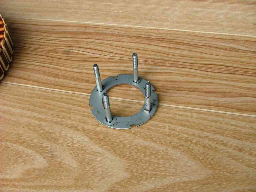
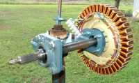
Once the paint has dried you can bolt
on the F&P stator
First grab a stator retaining plate
and 6mm Bolts.
Next the stator and other retaining
plate. |
 |
|
 |
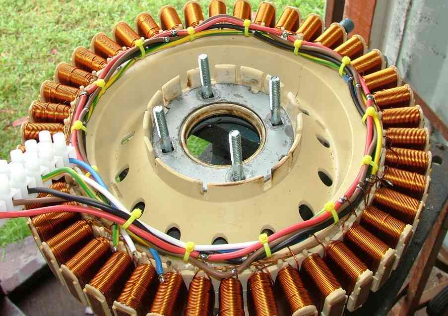
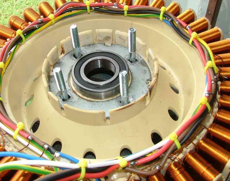
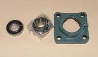
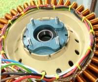
Tap the bearing into the stator.
|
 |
Slide on the bearing plate. If this
is too tight, remove the bearing from the stator and
tap the bearing into the bearing plate until flush,
then put back into stator as shown.

|
 |
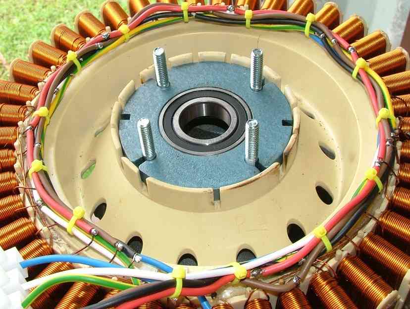
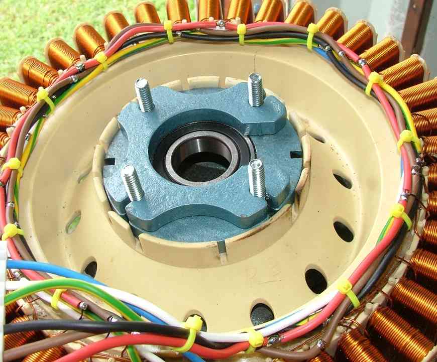
Place the bearing retainer plate. The
"Gap" is to clear the welding on the platform.

|
 |
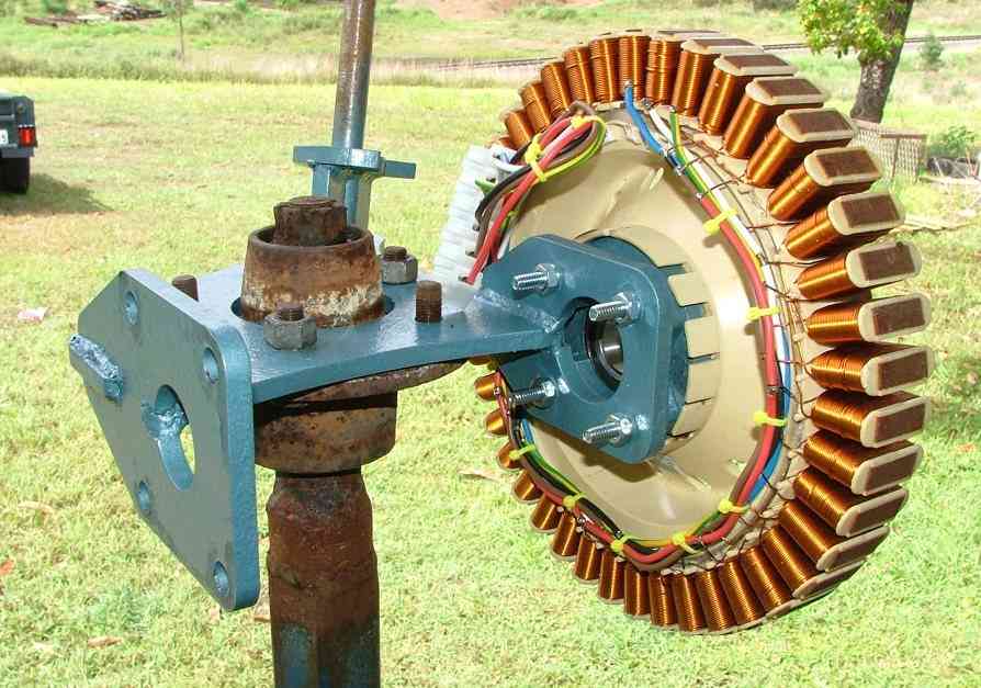
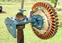
Bolt the stator onto the platform as
shown. Use lock washers and /or locktight.
|
 |
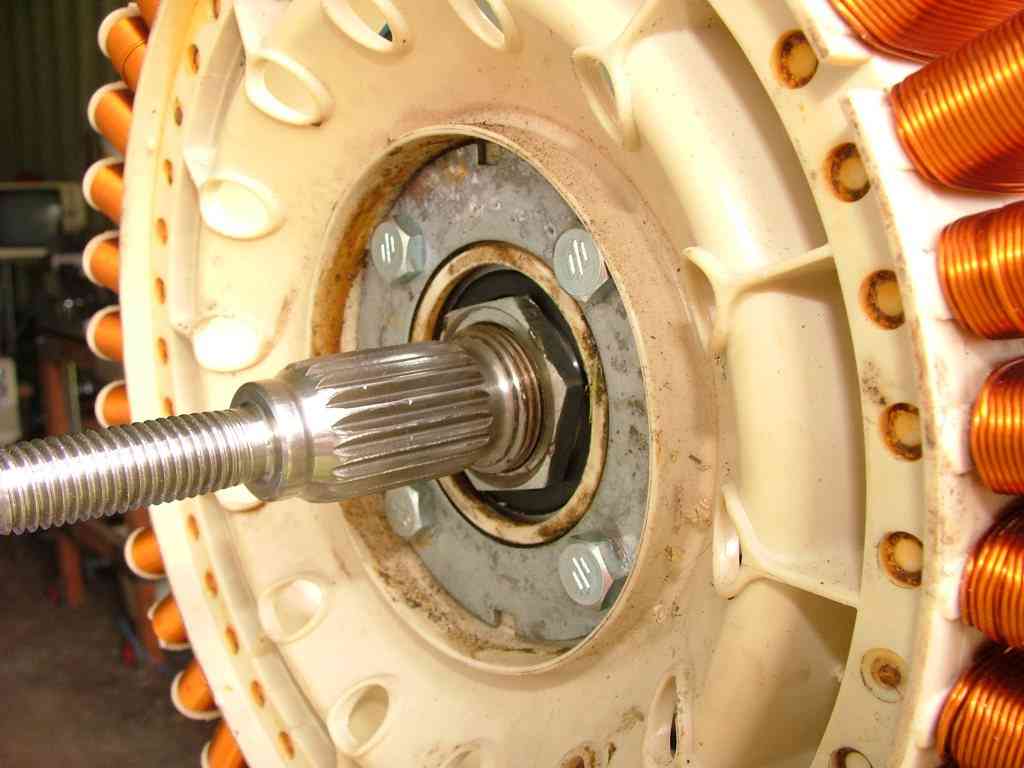
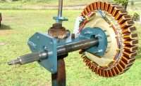
| Slide in the
F&P drive shaft from the back. The front end of the
shaft has the longer spline and will mesh with our propeller,
the shorter back spline meshes with the F&P magnet
hub. |
 |
| Fit and tighten
the shaft nut. Use Locktight to secure.. |
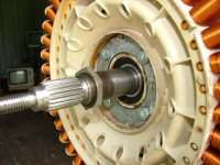 |
| Slide the shaft
forward as far as it will go. |
 |
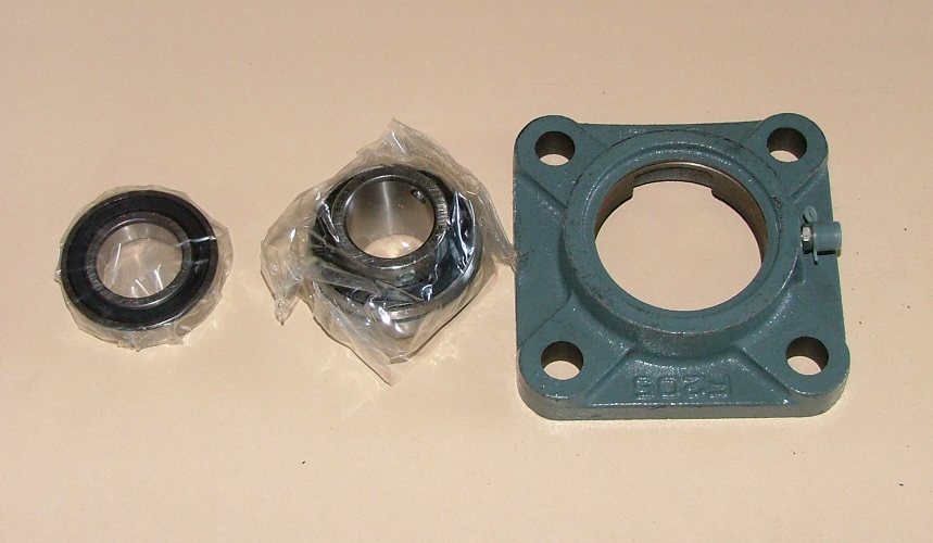
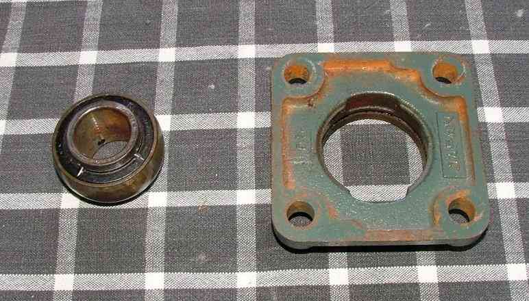
The front bearing comes as two parts,
the bearing and carrier. These need to be assembled,
which is easy once you know how ( It took me a while
to work it out!) |
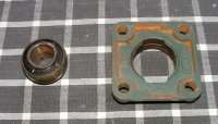 |
| The bearing
goes in from the back of the carrier. You need to pop
the bearing in at right angles to the carrier, and align
with the two slots. |
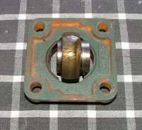 |
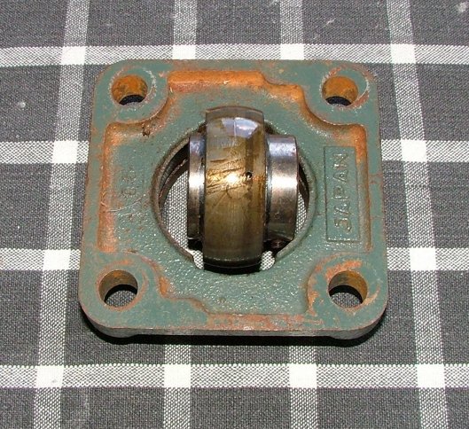
| Once in, rotate
the bearing... |
 |
| ...untill it
is home. A little grease will help and prevent rust. |
 |
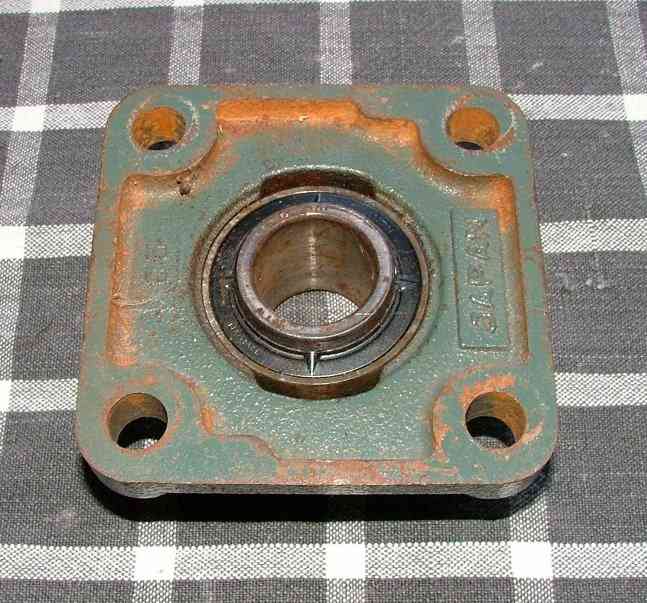
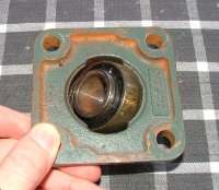
| Make sure the
grub screws on the bearing are facing out, as shown. |
 |
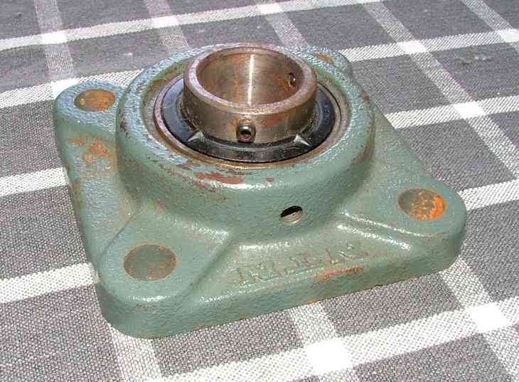
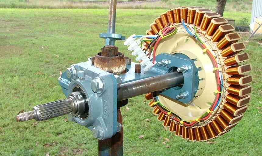
Slide on the main bearing and bolt to
the platform using the 12mm bolts, lock washers and
bolts.
Tighten the 2 grub screws onto the shaft,
and pump some grease into the grease nipple. |
 |
Test that the shaft spins freely. Temporarily
screw on the F&P magnet hub. Check again that nothing
is binding. Note - there will be a normal "cogging"
as you spin the hub. Also be careful of the electrical
connections as these will be live as you spin the hub.
Remove the magnet hub.
|
Next
- Propeller Blades
|