Notice. New forum software under development. It's going to miss a few functions and look a bit ugly for a while, but I'm working on it full time now as the old forum was too unstable. Couple days, all good. If you notice any issues, please contact me.
Am more concerned about the firmware , when will it be ready ?
Solar Mike Guru Joined: 08/02/2015 Location: New ZealandPosts: 1122
Posted: 10:24am 07 Jun 2019
Copy link to clipboard
Print this post
Good question, now that very few CPU IO pins are required, will see what small cpu's I have lying about and make a small board to do an initial test; looking in the cpu tin on the bench are several ATtiny85, 14, 18, 28 pin PIC's, some 32bit cpu modules arrived few days ago also.
For those less patient, then grab your Arduino or similar and have a go, gerbers etc for the other boards have been posted.
Currently renovating a house, new bathrooms, wallpaper, paint, so a little busy at the moment...
Cheers Mike
Solar Mike Guru Joined: 08/02/2015 Location: New ZealandPosts: 1122
Posted: 11:57am 12 Jun 2019
Copy link to clipboard
Print this post
Work continues; the main Lead Carbon bank (50v, 900 AH) will have 4 mppt chargers, one being a master, the others slaves and a spare, ie they will switch to bulk, float etc when directed by the master controller.
Have decided to use a form of 1-Wire bus system to network the PV controllers together, the master is also a form of slave in that it will be linked in to the BMS and the site control management system that monitors the 50 or so non-contact capacitance soil sensors for irrigation control. The 1-wire cable will be up to 500m in length with sensors clipped across its 3 wires (0v, +12v, Data).
I maybe asking too much of the cpu in the mppt controller to also talk to the external network, will have to try it out, the network wont be that fast, but may have to use a second cpu (ATTiny85) perhaps for this.
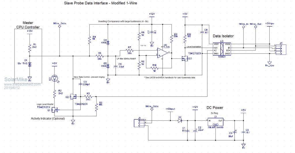
Anyway here is the proposed circuit of the 1-wire interface, it will be on its own tiny pcb that can plug into any of the slave devices, I have bread boarded some of it for initial tests, have used a data isolator chip for slave isolation as they are more immune to external interference than opto's.
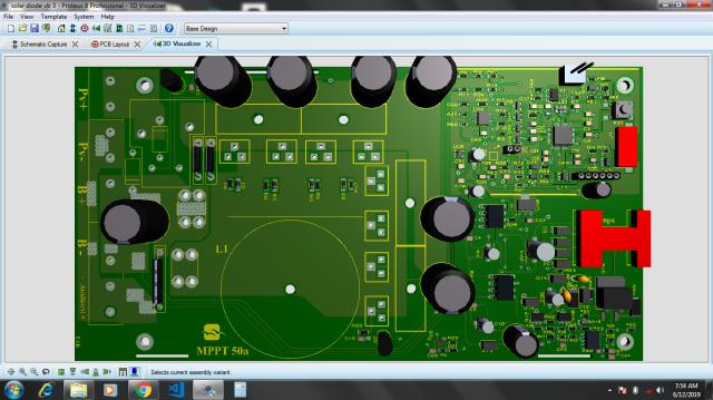
Almost done with my 50a PCB. I may adopt some part of your code. Currently adopting libresolar mppt project.
Solar Mike Guru Joined: 08/02/2015 Location: New ZealandPosts: 1122
Posted: 11:30am 13 Jun 2019
Copy link to clipboard
Print this post
The communications between mppt chargers is limited, switch to Bulk, Constant voltage or Float, so that wont be a problem. What Im not sure about is the comms between the Master charger and the rest of the network, will have to build and test. Depend on final cpu spec.
Cheers MikeEdited by Solar Mike 2019-06-14
Solar Mike Guru Joined: 08/02/2015 Location: New ZealandPosts: 1122
Posted: 11:47am 14 Jun 2019
Copy link to clipboard
Print this post
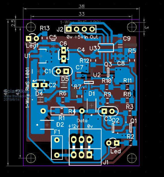
1-Wire PCB: I need quite a few of these, can fit 4 of them inside a 100x100 pcb, JLCPCB allows this if not panellised, cut them up with a guillotine no problem.
Cheers Mike
Solar Mike Guru Joined: 08/02/2015 Location: New ZealandPosts: 1122
Posted: 07:15am 16 Jun 2019
Copy link to clipboard
Print this post
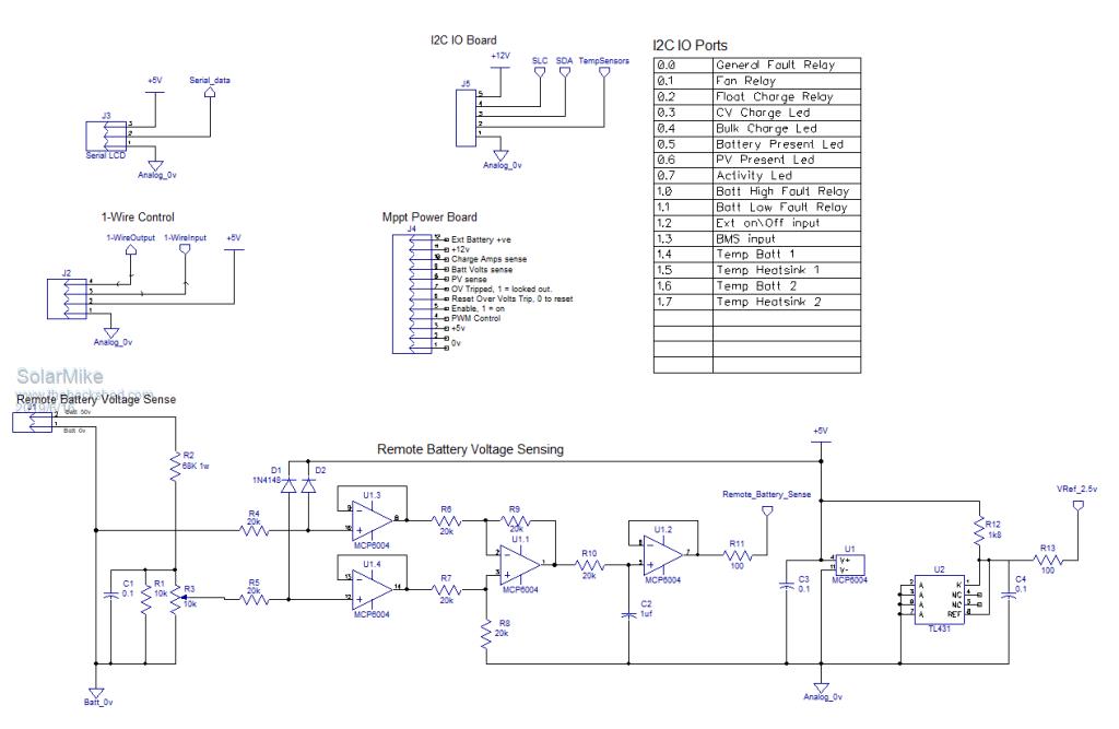
CPU board: Other than the cpu, there isn't much required for this board; the power mppt board connects via a terminal connector, the IO relays and temperature sensors connect via an I2C interface, the network interface is a modified 1-Wire connection and the LCD can be serial or I2C.
Because of the high charge currents, I think it is essential to have a remote sense of battery voltage, so have added a simple instrumentation circuit with gain of 1 to read the battery voltage at the battery bank terminals. (may put this on a tiny plugin pcb)
Also added a 2.5v reference that the CPU can use for accurate readings.
No CPU showing as I intend to try different types, need 15 free IO pins, have some PICs with 20 pins, try them first, then various Arduino's
After this prototype is running and debugged, the CPU board will be re-visited..
Cheers Mike
Solar Mike Guru Joined: 08/02/2015 Location: New ZealandPosts: 1122
Posted: 01:50am 11 Jul 2019
Copy link to clipboard
Print this post
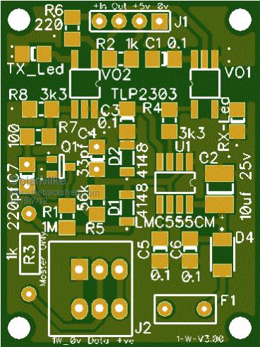
Isolated 1-Wire module that links multiple mppt controllers and the battery monitoring system has been simplified, now used a cmos 555 timer chip as the main data sense; using 4-8 volt hysteresis. Ditched the data isolator and now using fast opto-couplers, so it will all run off the 12 volt connection.
Original PCB was too big, see what happens with this design..
Cheers Mike
Solar Mike Guru Joined: 08/02/2015 Location: New ZealandPosts: 1122
Posted: 02:42am 12 Jul 2019
Copy link to clipboard
Print this post
New PCB is slightly smaller, but better laid out with a better isolation gap, without going to 0805 smd devices to reduce the size, will leave as is.
BenandAmber Guru Joined: 16/02/2019 Location: United StatesPosts: 961
Posted: 07:36pm 31 Jul 2019
Copy link to clipboard
Print this post
A lot of people say syncing a inverter with the generator is the Holy Grail
I think a good diy mppt charge controller Is the Holy Grail
Thanks for working on thisbe warned i am good parrot but Dumber than a box of rocks
Solar Mike Guru Joined: 08/02/2015 Location: New ZealandPosts: 1122
Posted: 08:50pm 31 Jul 2019
Copy link to clipboard
Print this post
I haven't done anything on this project for the past few weeks, lower priority, too many other projects, been working on a new battery management system that will work with both Lifepo4 cells and 6v lead carbon batteries.
I have fangpusun (victron) 150/70 mppt charger circuit . Hopefully to adopt some key circuits from it.
Solar Mike Guru Joined: 08/02/2015 Location: New ZealandPosts: 1122
Posted: 08:14pm 07 Oct 2019
Copy link to clipboard
Print this post
Last week finally bit the bullet and purchased a MMite Explore-28 module + its bigger brother, will do some experiments to see how suitable these 32bit machines are for running the mppt controller; as the old cpu board plugs in to the main mppt board, its easy to substitute another CPU.