
|
|
Forum Index : Solar : MinimuMppt
| Page 1 of 2 |
|||||
| Author | Message | ||||
| azhaque Senior Member Joined: 21/02/2017 Location: PakistanPosts: 117 |
Hi all, A minimum mppt CC design based upon Tim Nolan's work. Objectives Long term: Solar i/p 200 vdc, o/p 48 vdc, 75 amps. Current design 100 volts, 24 volts 50 amps. uC: Not yet decided but probably the Blue Pill STM32. Shall start prototyping after 14th June when I retire. Critique/Comments pls. 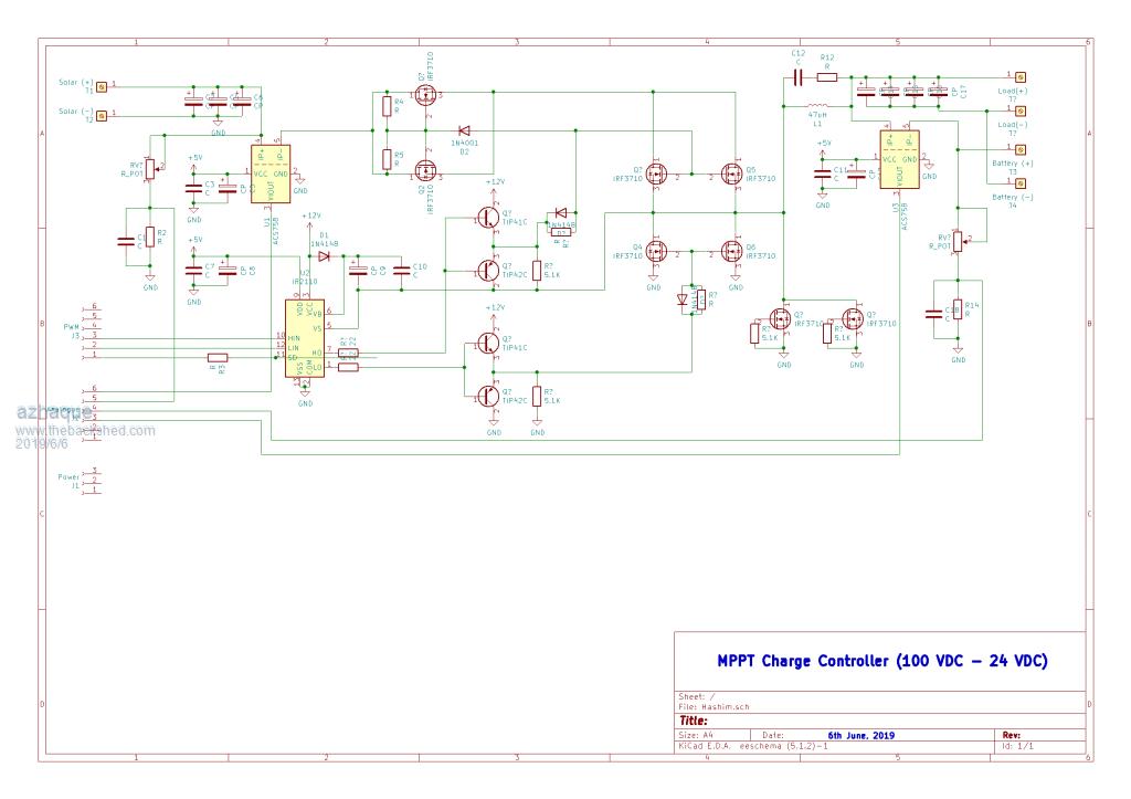 Regards azhaque |
||||
| davef Guru Joined: 14/05/2006 Location: New ZealandPosts: 499 |
Searching on Google for <Tim Nolan> certainly didn't get me to where I wanted!! Could you link to his work? Thanks, Dave |
||||
| azhaque Senior Member Joined: 21/02/2017 Location: PakistanPosts: 117 |
http://web.archive.org/web/20130430163911/http://www.timnolan.com/index.php?page=arduino-ppt-solar-charger Regards |
||||
| Solar Mike Guru Joined: 08/02/2015 Location: New ZealandPosts: 1122 |
Have seen this before, a number of designs have appeared on the net based on it. The PV isolation mosfets appear incorrect, as shown on your drawing they wont isolate the battery from discharging into the pv array due to the internal diodes. When swapped around so their sources are facing the PV, then their drive mechanism is iffy as they are being driven between drain and gate, so cannot see how that drive scheme will work out. The 2 mosfets with no drive are being used as diodes, not required as modern mosfet internal diodes are quite fast, if you are worried about that then use a fast schottky dual rectifier in their place. You will have to be very careful with the synchronous switching mosfets, if under very light charge conditions or discontinuous operation their duty cycle can get very large and reverse current flow from the battery into the main inductor reverse charging it to cause a voltage up converter spike when they turn off, possibly blowing up your circuit. Good start... Cheers Mike |
||||
LadyN Guru Joined: 26/01/2019 Location: United StatesPosts: 408 |
Salaam azhaque - I have recently made a post where Mike uploaded a unidirectional switch that addresses the internal diode issue. Are you going to share your circuit in KiCAD? Firmware on Blue Pill STM32 running Arduino will be excellent. If possible, please, I would like to break the circuit up into two separate parts - the MPPT part and the DC convertor itself - each will have its own CPU. 1. MPPT controller just runs the MPPT algorithm - we can hence try out the various ones available without upsetting the DC-DC Convertor 2. The intermediate voltage should be boosted to 400V DC so the internal wiring is manageable 3. We can then decide/switch out what topology of DC-DC Convertor to use. It's decoupled from the MPPT controller so the MPPT functionality is independent You want a buck to 24 volts (from 400v), I want a buck to 308V OR 170V (from 400v) followed by an optional MSW stage to obtain "AC" By building dedicated modules we build a highly reusable and resilient system. The price we pay would be the software overhead for two controllers to communicate with each other - this is a solved topic and Arduino comes with the required IPC primitives to make it really easy. |
||||
mackoffgrid Guru Joined: 13/03/2017 Location: AustraliaPosts: 460 |
Natasha, do you have references or links to IPC you're referring to. I usually avoid those situations but I'm curious. |
||||
| LadyN Guru Joined: 26/01/2019 Location: United StatesPosts: 408 |
Andrew, I would be more than happy to work on a test project with you to test these out. So for the ESP32 Arduino, they used FreeRTOS as the base OS, so we can reuse all the amazing things FreeRTOS has available for concurrency like queues to achieve inter task (and module) communication. The beauty of an FreeRTOS queue is that they already built in a lock into it, so we donÆt even need other synchronization primitives to ensure we don't corrupt the queue. This is a bit old but still userful: https://techtutorialsx.com/2017/09/13/esp32-arduino-communication-between-tasks-using-freertos-queues https://icircuit.net/esp32-inter-task-communication-using-freertos-queues/1946 |
||||
| Warpspeed Guru Joined: 09/08/2007 Location: AustraliaPosts: 4406 |
This is a VERY valid concern. Synchronous rectifiers are inherently bi directional and reducing the duty cycle can generate massively destructive voltages on the solar side. Synchronous rectifiers work fine driving a normal dissipative load, but when the load is a battery they can turn really vicious. I would use a conventional fast recovery diode and just put up with the one percent or so power loss. Anything is possible, but you are going to be making problems for yourself the way it is now when the software backs off the duty cycle, it is very likely to go bang. Cheers, ĀTony. |
||||
| mackoffgrid Guru Joined: 13/03/2017 Location: AustraliaPosts: 460 |
Ah, FreerTos - I've never used it. I'll resist for a while yet  In a micro-controller application I prefer to keep things simple, easier for me to get my head around it. I do all my own task management. I know I'm resisting change but I will endevour to look at it. |
||||
| azhaque Senior Member Joined: 21/02/2017 Location: PakistanPosts: 117 |
First of all many thanks to everyone who commented. Mike, Thanks for the encouragement. There are 3 obvious solutions to the reverse current issue, that I have noted in my research on this Project. a) Relay and/or Schottky diodes. Relay is the easiest to implement. Since my max. target current is 25 Amps, relays are the easiest with the uC these switching these on or off as per requirement. The Schottky route is also easy, with the additional advantage that it is automatic. No need to program anything. The target panel voltage of 200 VDC would require two diodes in series, plus probably another string of 2 diodes in parallel to increase current capacity. In my view this maybe the preferred method, at lease in the 24 volt system. b) Another idea is to put the MOSFETs in the low side path instead of the high side. That should be easy enuff to implement. Should need a an NPN transistor to drive the gate, with the transistor drive coming from the uC. Since we have both i/p as well as o/p voltages and currents (also direction with the ACS758) being measured, it should be easy enuff using software, to shut down the MOSFETs under low light conditions. Two more ideas that I would like your views about: 1) Putting in a separate dedicated IR2110 to drive the isolating MOSFETS. Using the high side output of the second 2110 to drive the MOSFETs. 2) Look into the possibility of using an SCR. Haven't seen this being done, probably because of power wasted. As mentioned above having 2 Schottky diodes in series to sustain 200 volts may just bring the losses in the same ballpark as an SCR. But I maybe speaking too soon. Thanks for the guidance. I had read about this issue. That's why I added the two lower MOSFETs which Mike suggested I replace with Schottky diodes. I think I'll do that because it is low side so 100 volt Schottky diodes should be OK. Salaams to you too Natasha and your family. Link to the Kicad files below https://drive.google.com/open?id=1D8JSsazDKDdXwuKeNxtAfjdfPozpRpkM Please provide the link to the post where Mike uploaded a unidirectional switch that addresses the internal diode issue. Regarding the Arduino/BP I have decided to use Arduino first and then go onto the BP for the 48 Volts. But what you said elsewhere is also a possibility i.e. use the ESP32. The wifi thing in the ESP32 is a definite advantage. Moreso I have done an ESP8266, so the 32 is a natural successor. Can you please elaborate the tree propositions at 1,2 & 3 of your post copied above. A diagram to back up the same would help me understand better. Thanks again everyone. azhaque |
||||
| LadyN Guru Joined: 26/01/2019 Location: United StatesPosts: 408 |
http://www.thebackshed.com/forum/forum_posts.asp?TID=11367#134748 Please couple this with the HCPL3120 as driver and the stamp sized $0.80 WarpPSUs you can get on Ali. This will allow you to monitor the current and control the unidirectional switch as well. Ok I will. As long as you're targeting Arduino, we are half way there as long as you don't write assembly code. Firmware on Blue Pill STM32 running Arduino will be excellent - don't you have a few Blue Pills already? Did you get Arduino running on them? |
||||
| Solar Mike Guru Joined: 08/02/2015 Location: New ZealandPosts: 1122 |
The simplest way to provide bias for the PV-Battery isolator mosfet is to use an IR Led Photo-Diode array, drawing attached; drive it from your 12v pwm signal to the high side buck mosfet, thus whenever you are driving the buck switch the PV isolator will be turned on. No drive signal and its turned off isolating the battery from the PV. Note the PV input isn't isolated from the circuit only the battery, another mosfet would be required for complete isolation, not really required here. You could always use a relay to replace this mosfet, would have to be a high quality relay to switch 200v DC without its contacts burning up, mosfet would be cheaper. Schottky diodes will also work, depends on how much heat you want to get rid of. SCR - No, how do you turn it off... High side SW with PV-Batt Isolator: 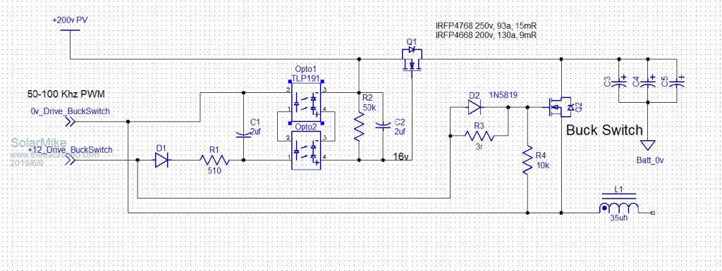 Cheers Mike |
||||
| Warpspeed Guru Joined: 09/08/2007 Location: AustraliaPosts: 4406 |
There are a few interrelated issues... Shottky diodes have a limited voltage rating, so as you have already said, two in series will be required. That really negates the shottky advantage of having low forward voltage drop. Might as well just use a single large ultrafast high voltage diode. That will be lossy, but in the great scheme of things the power lost will be proportionally quite small. One further thought. How hard the catch diode actually works depends on the duty cycle. It only carries current when the mosfet is off, so the duty cycle has a lot to do with the losses in the diode. The closer to 100% duty cycle you can run, the lower the losses in the diode. If you can reconfigure your solar panels for 100v or even 75v instead of 200v, that will make a significant difference to the operating duty cycle with a 48v system. You might even be able to get away with using a single shottky diode and lower voltage rated mosfets, and that will reduce Rdson. If you do decide to ditch the potentially troublesome synchronous rectifier, the voltage pump circuit usually used with the IR21xx isolated gate driver will have no way to start up. An isolated dc supply will be required to power the gate driver. Several different ways to do that, its really a matter of personal preference. Cheers, ĀTony. |
||||
| azhaque Senior Member Joined: 21/02/2017 Location: PakistanPosts: 117 |
Thanks Warpspeed, Yeah its all about tradeoffs isn't it. 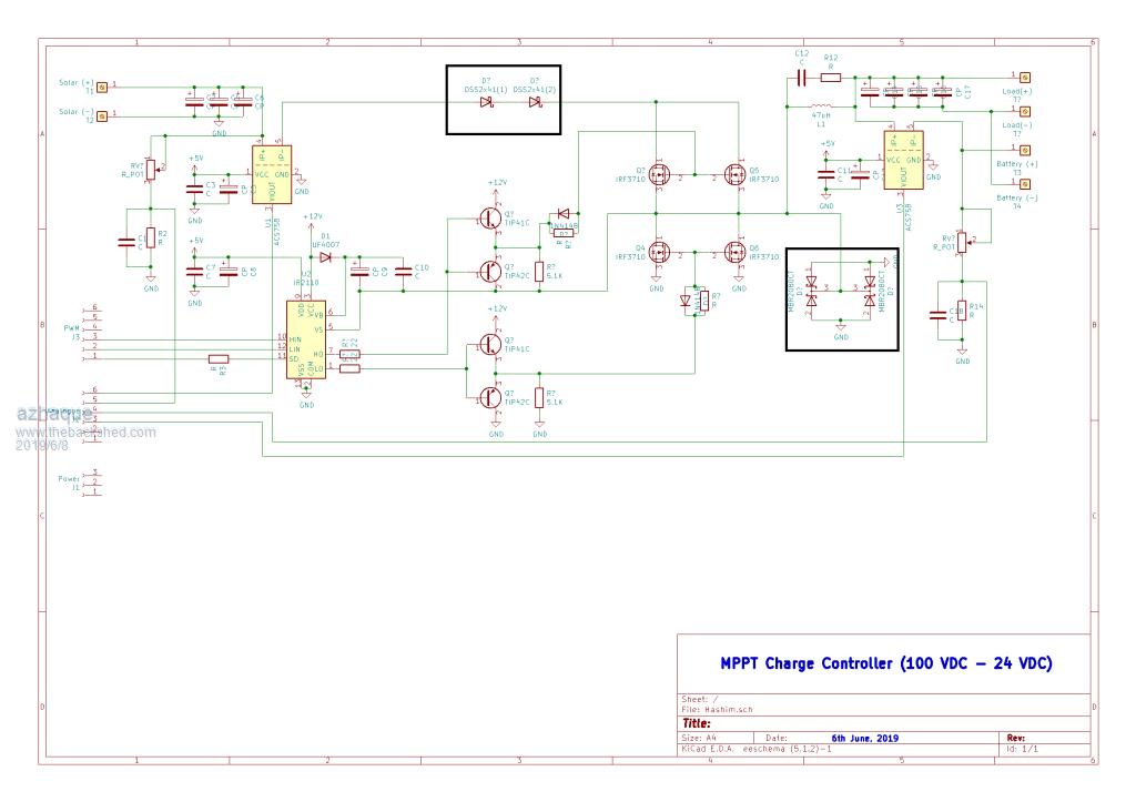 The above image is the MinimuMppt redesigned with Schottky diodes, both in the main current path as well as MOSFET protection during low duty cycle (both highlighted). azhaque |
||||
| LadyN Guru Joined: 26/01/2019 Location: United StatesPosts: 408 |
Here is a draft version of the ideas I have. If needed, I can split this discussion into a separate topic - just let me know! 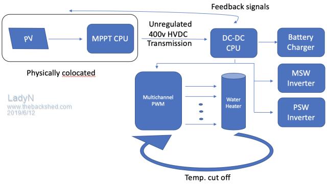 |
||||
| LadyN Guru Joined: 26/01/2019 Location: United StatesPosts: 408 |
The responsibility of the MPPT CPU is to focus on maintaining the PV array at power point. That is it. We would like to swap/try out the various power point algorithms and see which ones work best for our local environment. Since the MPPT CPU is decoupled from the rest of the system, we can easily swap the firmware or even the MPPT board if something does not work out as expected without affecting the rest of the system. This makes it easier than say, if the battery charging/voltage regulation/etc algorithm was also expected to run on it. This approach can also increase the chances of potential contributors because everyone needs a good MPPT board but some might need a buck, while others might need a boost, etc Also, there are some DC-DC boards already available online that we can repurpose. Another benefit is that we can colocate the MPPT CPU with the PV array - so we can use other techniques like pilot panel (to sample insolation), digital thermometer to sample ambient temperature, etc The unregulated 400v HVDC reduces the transmission losses making the system economical and efficient. The DC-DC CPU and MPPT CPU communicate over feedback signals. This can be wireless but to simplify development, we should start with wired. From there, the DC-DC CPU routes and regulates the power as needed. Since the DC-DC CPU is decoupled, we can easily swap the firmware or even the DC-DC board itself if something does not work out as expected without affecting the rest of the system. This approach can also increase the chances of potential contributors because everyone needs a good DC-DC board but they might not need an MPPT controller. Also some might need a buck, while other might need a boost, etc Also, there are some DC-DC boards already available online that we can repurpose. For most standard setups, the Battery Charger will be a buck convertor to 72/48/24v. Non standard setups will still possibly use a buck convertor, but to ~120V, which is what I plan to recommend my father do when LTOs become really affordable. At a regulated ~120V HVDC coming out of the DC-DC CPU, the P/MSW Inverters can be simpler than most standard designs. For example, the MSW Inverter can be completely transformerless! |
||||
| Warpspeed Guru Joined: 09/08/2007 Location: AustraliaPosts: 4406 |
That is one philosophy, but I am not convinced it is the universal solution. [quote]The unregulated 400v HVDC reduces the transmission losses making the system economical and efficient[/quote] Not necessarily. You first need to include the efficiency and power loss of both the dc to dc converters, as well as the cost. Will that beat just a straight piece of wire between solar panels and the various loads ? If the solar array voltage is suitably matched to the battery voltage and all the other loads, then you don't need anything at all, perhaps just a few diodes here and there to have a completely workable system. Ah! but I hear someone say, without mppt you lose efficiency. What is best, 5Kw of solar with mppt. Or 6Kw of solar an NOTHING ELSE. I would like to bet that four extra 250 watt panels are going to be cheaper and more reliable, and produce higher output most of the time if not always than trying to be really clever with 1Kw less from the power source. There might be a reasonable argument for mppt where space for solar panels is extremely limited, such as on a boat or RV. But for the usual roof mounted domestic off grid system I am not so sure that a massive amount of electronics can ever make up for having an excess of solar panels. Panels are now so cheap here in Australia that solar trackers and mppt are just not worth the trouble and expense for most situations. Cheers, ĀTony. |
||||
| LadyN Guru Joined: 26/01/2019 Location: United StatesPosts: 408 |
Yes, I agree. I should have stressed on the "see which ones work best for our local environment" in my above post. Local economic factors might very well render MPPT less valuable than purchasing more panels, but I want to see what MPPT costs me first. That is one big IF - my calculations show batteries, as they are priced in the U.S. right now, to be a losing proposition against 25c/kWh grid power and we pay one of the highest in the nation because of our rural locations. Matching the solar array voltage to all the other loads when there's no battery is not an easy task. The cheapest Grid tie panel here is typically a 250W, 30Vmpp, 9A Isc panel that wholesales for $150. A retail buyer like me has to pay extra on top of that. We cant afford that, so we purchase discarded panels that wont be sent in even for warranty, which are not as plenty in numbers and dependable in supply as we would like. Empirically I have proven it to myself that there is no EFFECTIVE way I can connect most loads to a PV array directly and expect good power output from the PV array: water heaters, power tools, pumps all drag the 150Voc, 18A DC PV array way down to half or less (an impact wrench or 220V electric heating element drags the array down to 2V DC) The cable runs to minimize losses for 18A is pretty expensive 10GA copper wire and I am sure some here are nodding their heads at the 10GA rating. We had to buy 150 feet of it and it wasn't cheap at all. I cannot see us purchasing such expensive wiring any longer. If I/we can make a HVDC boost convertor that takes 180V, 18A DC from PV and turns it into 380V, 9A DC for $200: 1. Is that a net negative financially? 2. IF NOT, can we design such a HVDC boost convertor for $200 in the first place or is that an impossible task? Tony, you're right - a MPPT controller might gain us 20% net increase in throughput but with higher voltages we are saving a lot more and losing a lot less. Plus, with a MPPT controller I'm now less tied to matching loads to my array compared to direct tie where I cant even heat a gallon of water with 1kW of panels! I have a bunch of homework this week and the next but I plan to have some calculations that compute the area under curve for various scenarios. I have to do that anyways to design the transformerless MSW inverter that runs directly off PV array. Summer is fast approaching and we will need to run fans atleast! |
||||
| Warpspeed Guru Joined: 09/08/2007 Location: AustraliaPosts: 4406 |
[quote]I have a bunch of homework this week and the next but I plan to have some calculations that compute the area under curve for various scenarios.[/quote] I strongly suggest you do some real world practical testing using a solar panel with a power meter and an adjustable dc load. The power obtained will not be a sharp peak, but a very low broad hump. Try this under various conditions, clear blue sky, dawn/dusk twilight, and full evil grey cloud. You will discover the solar panels work usefully over a reasonably wide voltage range which does not change very much under the most extreme conditions. The available current changes hugely, but not the optimum operating voltage range. All mppt does is limit the current loading to what the panel can produce, so keeping the panel voltage fairly constant. You can do pretty much the same thing by just connecting the panel direct to a battery. If the solar panel array and the number of battery cells are carefully chosen, you really do not need anything else. If you want to make a 380 volt system, just do it. Twelve 24 volt panels series connected might be about right. A matching 380 volt battery, and a 380 volt dc input inverter. You don't need multiple dc to dc converters or mppt. All the wiring will be for low current and it will be SIMPLE, reliable, low cost, and efficient. What really opened my eyes to all this was a rather rough solar panel tester I built up a very long time ago. It uses a low cost Turnigy power meter that measures volts, amps, watts, watt hours, and other things. This is what I used, but there are plenty of similar alternatives. https://www.ebay.com.au/itm/Turnigy-130A-Watt-Meter-and-Power-Analyzer/223545304077?epid=1276854821&hash=item340c56a40d: g:1EkAAOSweZ9chVdC The output of the power meter is connected to a large electrolytic (22,000uF 63v). There is a mosfet and a discharge resistor connected across the electrolytic (2 x nine ohm radiator bars in parallel). The mosfet gate is driven by a 555, and the output duty cycle of the 555 can be potentiometer adjusted from 0% to 100% duty cycle. 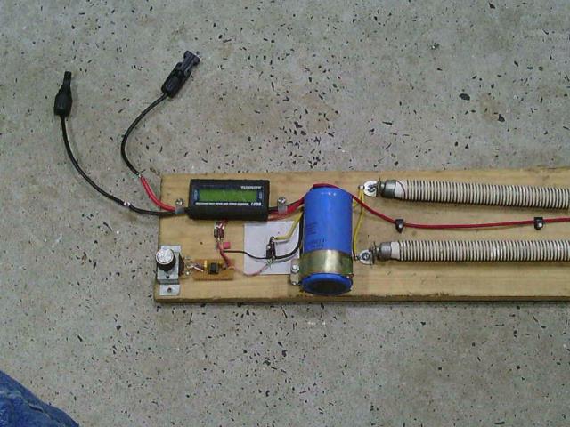 By tweaking the pot, I can adjust the loading on the solar panel from no load up to about a 4.5 ohm maximum loading. For a 24v panel that would be about 30v and 6.6 amps, about 200 watts. That is about what I expected to get from a 250 watt panel which turned out to be spot on. Cheers, ĀTony. |
||||
| LadyN Guru Joined: 26/01/2019 Location: United StatesPosts: 408 |
thank you Tony. What's the function of the large electrolytic there - it acts as a fast discharge capable energy reservoir that modifies the stock behavior of the PV Array - does it not? |
||||
| Page 1 of 2 |
|||||
