Notice. New forum software under development. It's going to miss a few functions and look a bit ugly for a while, but I'm working on it full time now as the old forum was too unstable. Couple days, all good. If you notice any issues, please contact me.
Forum Index : Solar : PV PWM Charge Controller, is mppt operation possible
Author
Message
Solar Mike Guru Joined: 08/02/2015 Location: New ZealandPosts: 1123
Posted: 10:00am 07 Aug 2019
Copy link to clipboard
Print this post
I have a thought experiment that requires team input: Can we take a standard PV charge controller that operates with PWM to control battery charge and modify it so that the control circuit can alter the loading on the PV array such that mppt operation is achieved and without turning it into a buck converter, ie no inductors.
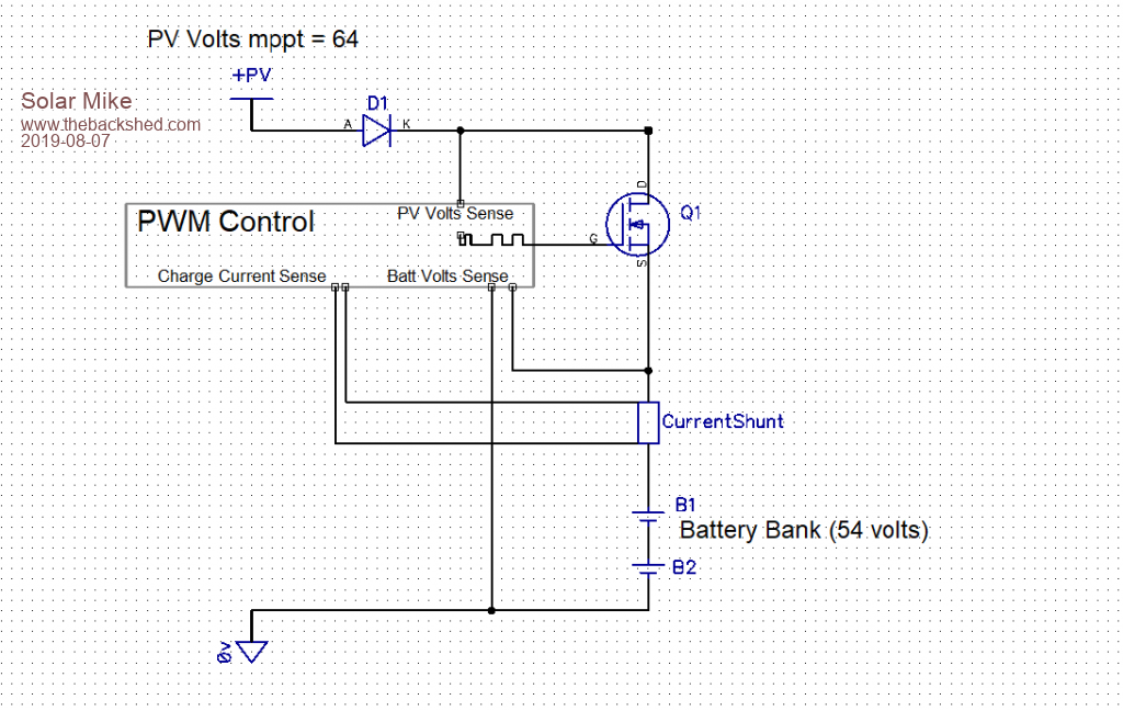
Here is a basic block schematic of a PWM charge controller, diode D1 isolates the PV array at night, preventing the battery from discharging. Mosfet Q1 is switched on by PWM (pulse width modulation) to either limit average charge current and or battery voltage.
If the battery bank has a bulk charge say to 54 volts (lead acid gel) and the 2 series PV panels output 64 volts at mppt point at say 10 amps, then our flat battery = 48 volts will pull the PV voltage down to 48 @10 amps = 480 watts input. Potentially loosing 64-48 = 16v @10 amps = 160 watts, as the battery charges to 54v then input power = 540W, so potential losses drop to 100W.
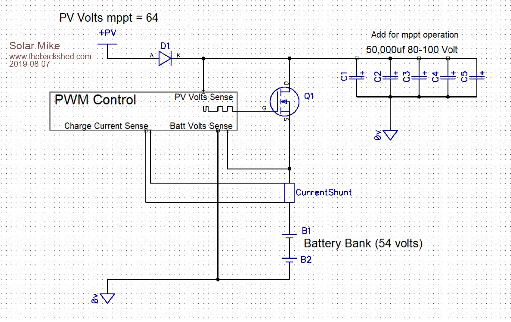
Now what would happen if a big bank of capacitors was added to the circuit:
If the controller monitored the charge current, battery voltage and the PV (big cap) voltage, it could real time modify the PWM duty cycle to maintain max power going into the battery; the capacitor bank supplying a higher current than the PV array could output. This would in turn provide a better constant load match on the PV panels, so increasing their output.
Noted it would still pulse the charge current into the battery unlike a buck converter that uses the inductor to smooth out the ripple current. I don't think 1000AH batteries mind current pulses too much.
This is a bit like the discussion on pulsing PV derived current into the HWC element and would work in a similar way.
Any thoughts....
Cheers Mike
Davo99 Guru Joined: 03/06/2019 Location: AustraliaPosts: 1577
Posted: 11:37am 07 Aug 2019
Copy link to clipboard
Print this post
As ignorant as I am in electronics, I have had the same thought having not given up on my idea of using pre made boards for controlling the heating element.
I have been looking at different charge controllers and PWM controllers that don't use an inductor which in my clueless mind would make it hard to PWM a mosfet.... although I am learning all the time and now realise there may be ways around that.
While I am waiting on parts to arrive to build Tony's design which is a safe design to work, I have been ordering other bits and pieces to see if I can somehow work this out with premade boards as I have got a bee in my bonnet about that. Seems there are so many of them it should to me just be a matter of working out a combo to do the job and hashing them together.
I see the advantage in having caps and that was definitely a part of my idea for this. I found another mysky inverter on the weekend and there is not much about what goes wrong with them on the net. Cheapest I can Find the relays for the thing is about 12 bux each and $50 is more than I am prepared to take a chance on so I can harvest another 6x 1000 Uf 315V caps out the thing at least.
In my mind, all that is needed for the direct PV to heating element is an automatic voltage monitoring switch which some of the premade boards seem to be set up to do.
Was your design based on a Pre made Board Mike? I haven't seen any that do Current and Voltage in what I have looked at.
Solar Mike Guru Joined: 08/02/2015 Location: New ZealandPosts: 1123
Posted: 11:52am 07 Aug 2019
Copy link to clipboard
Print this post
No Mate I design all my own boards, then I know exactly what I'm getting.
Cheers Mike
nickskethisniks Guru Joined: 17/10/2017 Location: BelgiumPosts: 410
Posted: 12:37pm 07 Aug 2019
Copy link to clipboard
Print this post
The only way is to test this setup against a charger with mppt. I think the only thing that needs Care is to have cycle by cycle current limit to protect the fets.
I was thinking, will the Massive capacity not make it more expensive then a real buck converter? And output voltage meassuring harder to track with Massive current peaks?
Warpspeed Guru Joined: 09/08/2007 Location: AustraliaPosts: 4406
Posted: 10:54pm 07 Aug 2019
Copy link to clipboard
Print this post
There is an assumption here that if the mppt point is 32v and 10 amps that if you pull the voltage down to 48 volts, you can still only get 10 amps.
This is not in fact what happens. The solar panel may very well deliver the promised ten amps at 32v, but if you load it up more, the voltage falls and the current increases. And the current keeps on increasing right up to placing a complete total dead short across the panel.
Below the maximum power peak, the power does not fall away as quickly as many people believe. I did some testing a few weeks back of a 24v 200 watt panel, and the figures (as I remember them) were that the power peaked at 32v, and only dropped by 10% at 36v and 26v. All this is buried somewhere in the hot water thread.
So there is a massively wide voltage window of perhaps ten volts where you only lose 10% of the power at the voltage extremes. That should charge a battery perfectly well without using anything else.
There is only the problem of how to prevent overcharging, or have some way of controlling the final "absorb" part of the charging cycle where the voltage needs to be held just below the point where excessive gassing commences.
That could be done with a shunt resistive load to absorb the excess solar power. Either resistors could be sequentially switched in, or a resistive load could be switched on and off with PWM. That could be done without any inductor or drama.
Switching a charged up capacitor bank directly to a battery is going to result in some spectacular current spikes, and is not recommended. The choke in a buck regulator is there to prevent that.
But you can switch a resistive load on and off without the current spikes.
Or you could have say four resistors, weighted in binary to create 16 load steps. That would be far more gentle and progressive. Eight resistors would produce 256 load steps which I suspect should work rather well as an adjustable shunt load.Cheers, ĀTony.
Warpspeed Guru Joined: 09/08/2007 Location: AustraliaPosts: 4406
Posted: 12:23am 08 Aug 2019
Copy link to clipboard
Print this post
Just found the figures for my solar panel testing in the hot water thread.
Cheers, ĀTony.
Solar Mike Guru Joined: 08/02/2015 Location: New ZealandPosts: 1123
Posted: 12:48am 08 Aug 2019
Copy link to clipboard
Print this post
Cool thanks Tony, I checked the specs of the panels we are going to be using, Imppt = 8.86 amps, Ishortcircuit = 9.43.
Right I will leave as is and stick with the simple basic PWM for this application, the current spikes are already pretty high and introducing a capacitor bank to simulate some mppt action is not worth the hassle.
System will always have a load on it, so reducing the PWM duty cycle which will lower the average charge current should keep battery voltages constant.
I quite like the idea of using a shunt regulator to keep absorb voltages constant, especially if the load was a 50V HWC element, divert the excess power into the HWC tank.
Cheers Mike
Warpspeed Guru Joined: 09/08/2007 Location: AustraliaPosts: 4406
Posted: 12:58am 08 Aug 2019
Copy link to clipboard
Print this post
I never actually considered using the power dissipated by the shunt regulator, but that is an excellent idea.Cheers, ĀTony.