
|
|
Forum Index : Solar : Solar buck converter
| Page 1 of 2 |
|||||
| Author | Message | ||||
| nickskethisniks Guru Joined: 17/10/2017 Location: BelgiumPosts: 411 |
Hello, It's been a while since I posted something so there will be a lot of spelling mistakes  Last summer I didn't need something to maximize my solar input, but winter is coming and we don't have a grid connection (anymore). We bought half of an old farm and last 3 years we spent renovating it, we can say it's more like a new build house because except the front wall it's all new. We bought the piece without grid connection... Getting a new grid connection is not an issue, it's "only" about 1200�. For solar owners there are uncertain guidelines on this moment, the introduction of the digital meter gives many owners a lot of stress... One thing is for sure, we will pay to use the grid as battery... and there is no one that will tell you how much... So we will try to manage without as long as possible hobbywise... untill we have no choice or guidelines are fully understand. We are living in Belgium so it will not be easy to harvest enough energy during winter. We need to do it with 48V 400Ah SLA and 51.2V 400Ah Lifepo4 and 27 panels of 280W. Heating is done with a wood stove called tulikivi raita 18 and 12m� solar thermal panels, they all are connected to 800l buffer and the floor heating. All electric apliances are new and energy effici�nt. I guess it would be possible if we were not cooking on electricity. I probably need to buy a small generator or more panels. So the solar, String 1 is 6 panels 280W, String 2 is 6 panels 280W and String 3 is 8 panels, wired in 2 series/parallel so optimized to be used with 48V. But we have shading until midday. The 4th string are 7 panels 280W in series attached to a grid tie inverter, that's connected to my Ozz inverter. The 48V strings are " controlled" by a big contactor. So I wanted to make 3 "simple" controllers for 48V and max 40Amps, yes today you can buy good controllers for that but whats the fun in that. �  I used this site for guideline: https://www.daycounter.com/Calculators/Switching-Converter-Calculator.phtml But the last year I read every post of warpspeed and solar Mike, allways verry good comments and insides! So this year I made a few experimental buck converters, and guess what the most simple concepts worked best  . Once I made a verry simple design with just one irfp4110 a diode and 2 caps with long wires to an arduino nano with a tlp250, it worked for months, I put it out of service now. . Once I made a verry simple design with just one irfp4110 a diode and 2 caps with long wires to an arduino nano with a tlp250, it worked for months, I put it out of service now.I did experiments with snubbers, cycle by cycle current measuring with current transformer (difficult with high duty cycles). All kinds of inductors, capacitors,... I learned a lot, didn't blow up things tho.... I made a pcb in july this year, finaly got it tested today! Software is written verry poorly in arduino, but it works, it's just a litle bit slow when I disconnect the battery, so the output voltage rises to much, thats just software. So I used 2 parallel mosfets (irfp4110), 2 dual body diodes 30cpq100 in parallel. For gatedrive I used 12ohm resistors on each gate to a tlp250. Switching is done on 31khz. The inductor is an etd59 with about 100uH, it has 1mm airgap. I tested to about 62Amps going to the battery, @ about 40Amps there was 15% more current going in to the battery! With 30 amps there was no cooling needed, with 60 amps going in to the battery, a fan was required to cool the inductor. I only made it for 30Amps (4amps/mm�). I used 9 elco's epcos 1000uF 300V on the input and 5 the same type on the output, I have hundreds of those laying around, NOS from ebay.... Also 4.7uF MKT on the input and output. ACS758-100 was used to measure in and output current. The concept could be verry easy adjusted to other input/output parameters. Code is like this: � if(UoutPut < UsettingOut) { �pwm = pwm +1; �pwm = constrain(pwm, 1, 254); } if (UoutPut > UsettingOut) { �pwm = pwm-1; �pwm = constrain(pwm, 1, 254); } Simple but it works, Usetting is done with a potmeter, and read on an analog pin, I use 62V for my panels. 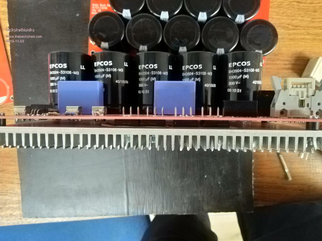 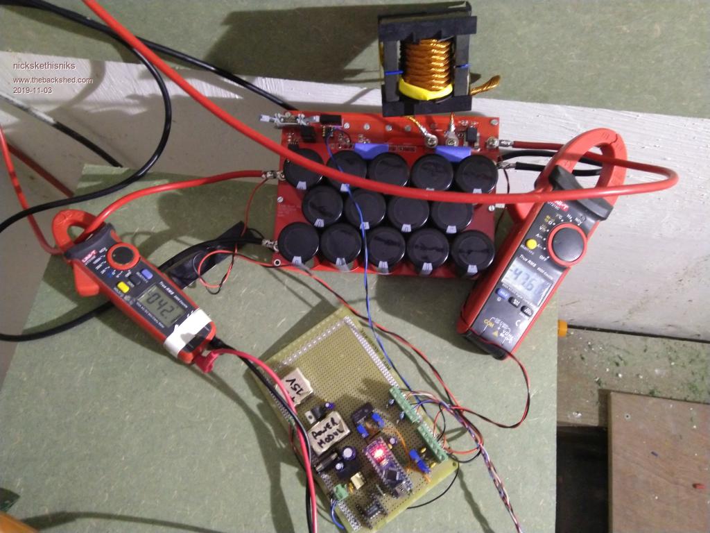 The pcb was drawn with EasyEDA, I know it's a chaotic post, I will give more details like schematic, gerbers if wanted and code next time. I'm happy with the result that's why I want to share it with you guys! Any help how I could improve it is welcome! Edited 2019-11-03 08:41 by nickskethisniks |
||||
| Warpspeed Guru Joined: 09/08/2007 Location: AustraliaPosts: 4406 |
That is a truly great effort there Nick. Its now just a case of tuning up the software  Belgium is going to be just a little bit different to Australia! Probably the biggest issue will be how many cloudy days in a row you are likely going to strike in winter. There is no substitute for local climate experience. That is going to be the killer, and when the sun stays away for several days in a row, more panels or a larger battery are just not going to help. I believe a battery charging generator of some type is going to be a necessity at some times, even if its not very often. Until you have experienced at least one winter, its not going to be really possible to estimate your typical consumption or solar input with shorter days and longer nights. Cheers, �Tony. |
||||
| nickskethisniks Guru Joined: 17/10/2017 Location: BelgiumPosts: 411 |
Since I want to keep everything safe for myself and others it will need an enclosure. So I thought why not using an old grid tie inverter for that. It looks like the old casing will house 3 converters just fine. So I will have inputs for 3 strings, and the outputs of the converters will be paralleled after a series schottky diode. Maybe I put in a fuse on the output, the solarstrings are allready fused. The heatsink is about 32*54*6 cm so there will be no active ventilation needed, de �pcb I made has solderpads to connect 2 Ntc's for tracking the heatsink and inductor temperature. The �c controller can act when there are things out of range. 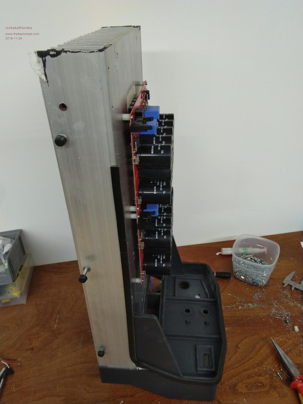 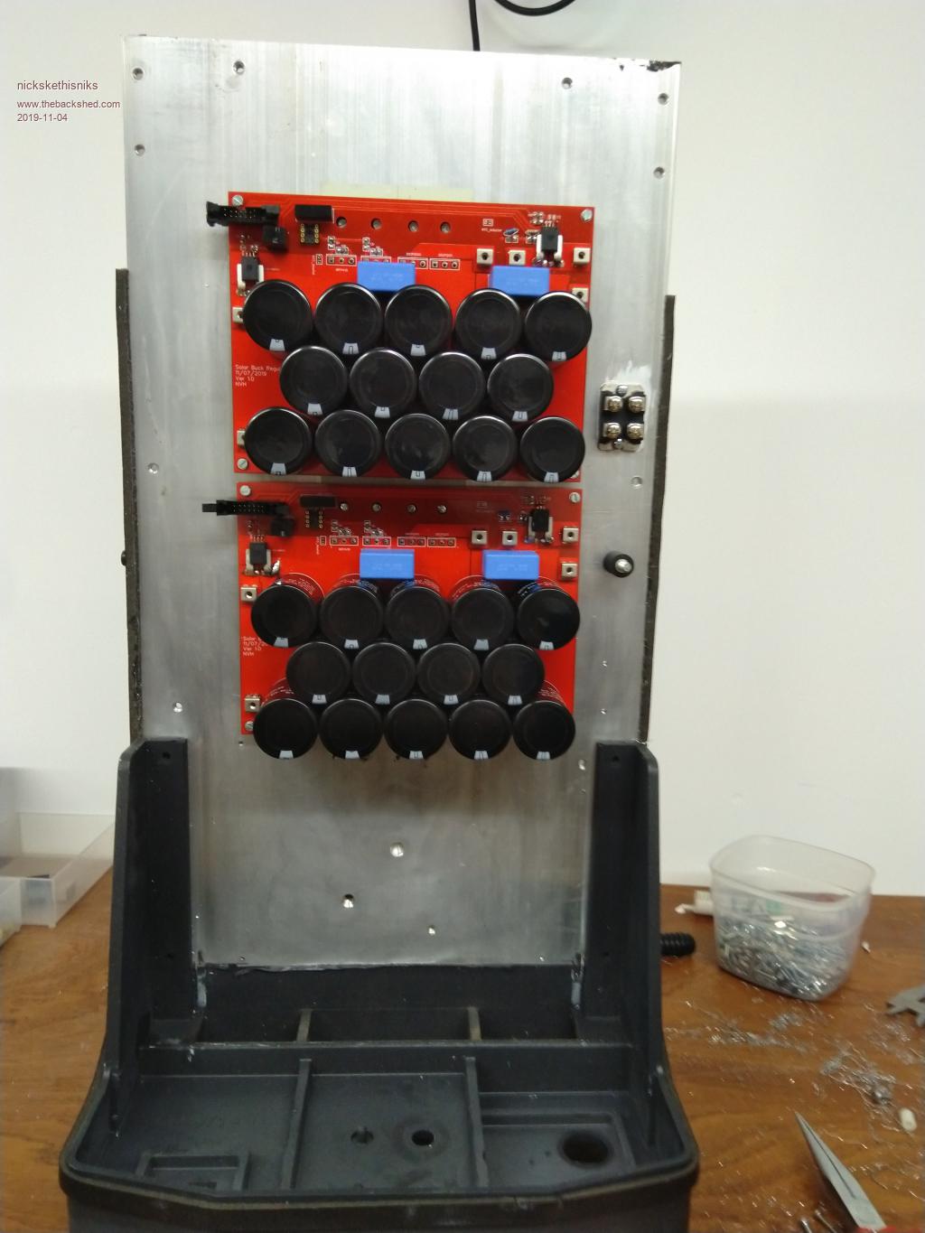 The inductors will be placed on top of the capacitors. I hate this part of a project, spent hours to drill an tap those holes.  It's verry hard to finish projects, I hope I could get this job done. Edited 2019-11-04 06:59 by nickskethisniks |
||||
| nickskethisniks Guru Joined: 17/10/2017 Location: BelgiumPosts: 411 |
Well, I got sick the other day. My body is empty, pushed it to far I geuess. It was a hard year, so I need to throtle back somehow the coming weeks/months. This week I took a few days of and next week my parental leave (2w) starts. I will become a dad for the first time, my wife was calculated for the the second of november... So back to the project, the breakers are just for reference, I need to buy the right values. Thinking about it now, it would have been better to place one after each converter. Saved by the sun today, we had 6 days of really clouded days in a row. So the lifepo4 were as close to empty @ 3V/cell. Can't estimate the level of the lead acid ones @2V/cell. I think we know more after this month. Today we will do break even, better days to come they say. Maybe next week I will have a play with a rpi to see if I can monitor my system on a easy way. 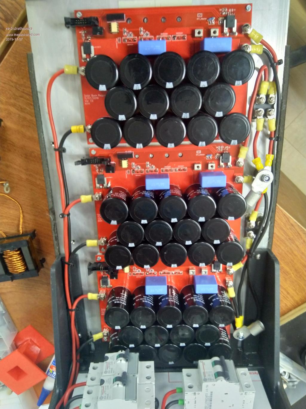 Edited 2019-11-07 23:20 by nickskethisniks |
||||
mackoffgrid Guru Joined: 13/03/2017 Location: AustraliaPosts: 460 |
Hi Nick, Very nice. You explanation covers it pretty well. A schematic is probably not important but would be nice if you've done one. I'm playing with charger design atm (higher voltage though) and was debating with myself whether to use a uProc or dedicated controller. Seeing this post I'm going to try the uProc approach first. BTW, Do I spot a 3d printed former  Cheers Andrew |
||||
| rogerdw Guru Joined: 22/10/2019 Location: AustraliaPosts: 794 |
I have to agree with the others, a great looking project and looks like you've done lots of homework. Awesome. Most of this is new to me ... so what sort of money do you have to pay for a mainstream 48V @ 40A controller? Is that Litz wire in the inductor ... or something you combined yourself. I kept a heap of old Panasonic Inverter Microwave transformers for the Litz wire on them ... though don't think I've ever unwound one to find out just how much is on each one. I'll be following this thread with interest. Cheers, Roger Cheers, Roger |
||||
| nickskethisniks Guru Joined: 17/10/2017 Location: BelgiumPosts: 411 |
Hi there, Yes that's a 3D printed former, a colleague of mine has one. I bought those big ferrite cores, but couldn't find the formers. I'm going to build a new series inductor for my ozinverter. I combine the wire myself, I used 0.56mm wire, so @ 4A/mm� that is about 1A per wire. I then put them in a vise and twist the wires togheter with a drill. A few years ago bought a small litz wire bobbin, think it was 200gr for 30�!  I'm not doing that anymore! There is a small company (Bobimat) that's selling all sorts of wire and spools for making transformers nearby. There I payed about 140� for 12kg enamelled wire rated for 180�C. For my inverter I did this too but I had to buy a spool of 42kg... that was 10mm� wire. 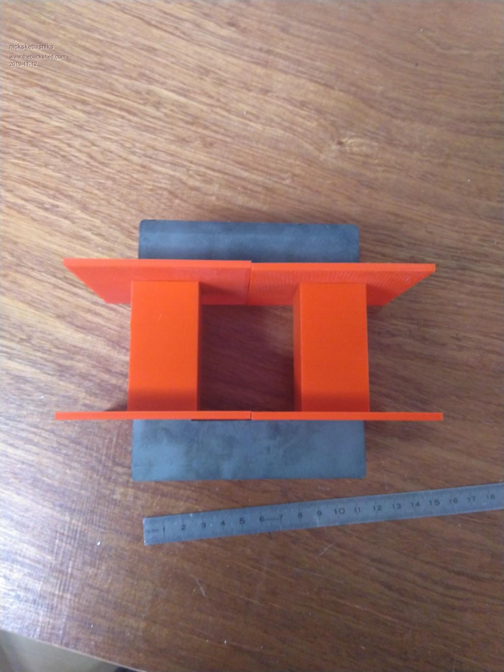 I don't know if you could build this cheaper then a commercial controller. I made a schematic, normally I just do it on paper, it's faster that way, but I need to do it more in the future. For more complex pcb's there's no other way... I didn't used parallel diodes on my gate resistors, and no snubbers on diodes and mosfets. I don't think they are needed, mosfets and diodes are overrated for my use (48V 30A). With some inductors I experimented with, there were some really nasty spikes on my input and output capacitors. But ones the inductor was well designed (overdimensioned maybe) they were as close to zero. This one for example worked verry good, but gave a lot of high spikes: https://www.tme.eu/be/nl/details/dtmss-47_0.10_30-v/ringvormige-smoorspoelen/feryster/ I had it for a half year in a test rig, maybe it would be better with higher frequencies. Not sure about all the values, the filter on the ouput of the current measuring is not tested. All measured values are going in a differential amplifier before they are going in the uC. There was something about the outputcurrent of a �C, about sinking and sourcing capability. It could be important when driving an optocoupler @ high speed. 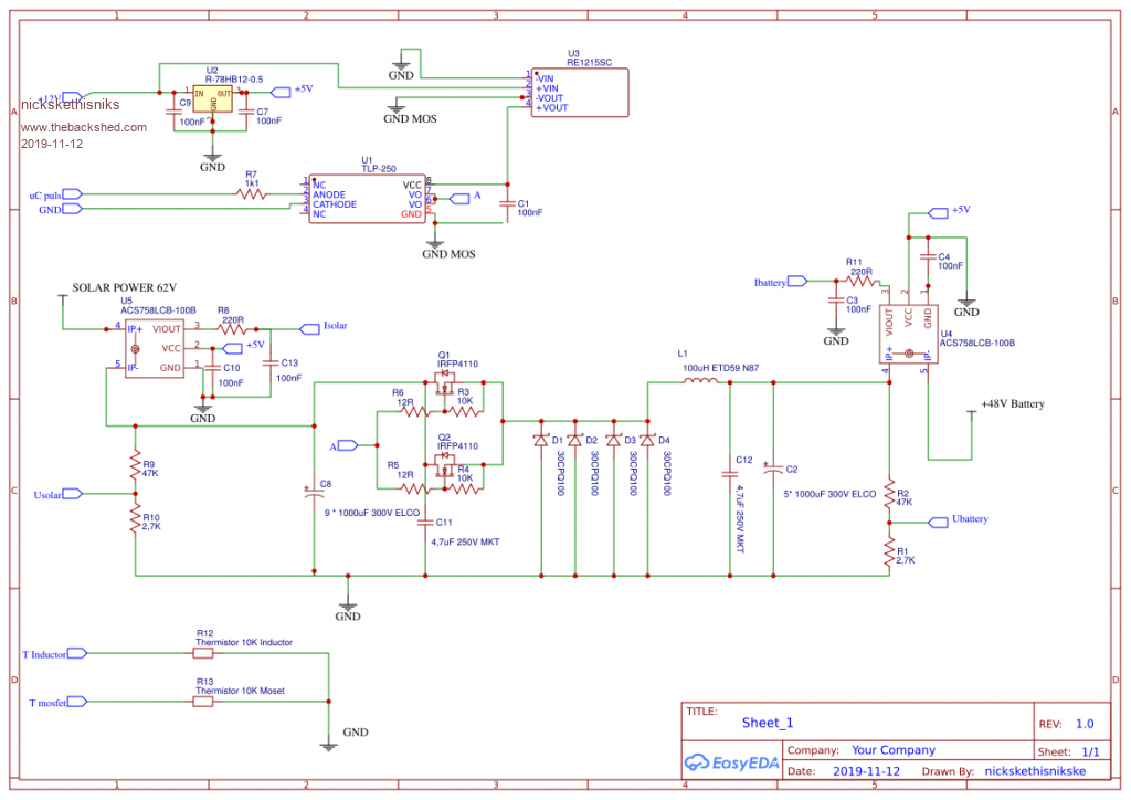 Edited 2019-11-12 22:34 by nickskethisniks |
||||
| nickskethisniks Guru Joined: 17/10/2017 Location: BelgiumPosts: 411 |
The prototype version is still going strong, but I still need to draw the controller pcb. Today I saw 84A peak, good for more then 4600Watts in to the battery! The unit is fused with a 63A breaker so it allows this kind of peaks. I must say the inductor is cooled actively, at this kind of power it gets hot, +/-90�C. And important, the tracks are short but the board is only 1oz thick, so the pcb is getting hot as well. The unit is now running allmost 2,5 months without problems. There is 5600W panels connected. The final install will be verry conservative @ 40A max per unit. Edited 2020-02-17 23:40 by nickskethisniks |
||||
| Warpspeed Guru Joined: 09/08/2007 Location: AustraliaPosts: 4406 |
That is an excellent result. Using multiple controllers is a very good solution to spreading the heat, and it also provides some redundancy if you ever need to work on part of the system. It may not end up being all that much cheaper than a Chinese magic mystery box, but at least you will be able to repair it, and fine tune the software to do exactly what you want. Plus there is the satisfaction of doing it all yourself. Cheers, �Tony. |
||||
| nickskethisniks Guru Joined: 17/10/2017 Location: BelgiumPosts: 411 |
Thank you Tony, Well it's a cloudy day so why not spamming on this forum. Picture of the 3 new inductors, 40 wires parallel for 40A. It's now 1,8mH but the airgap needs to be adjusted for higher saturation point and the right inductance. 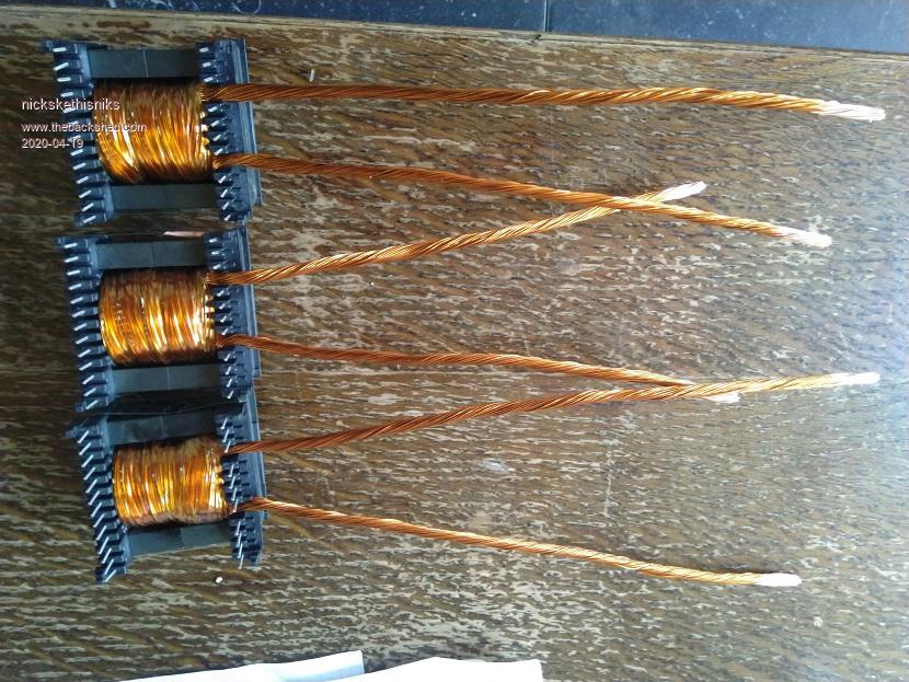 |
||||
wiretronics Newbie Joined: 26/04/2020 Location: NigeriaPosts: 5 |
Hello Nick, Could you please share the files for this project as I'm interested to build it for my new home. |
||||
| Warpspeed Guru Joined: 09/08/2007 Location: AustraliaPosts: 4406 |
The rule of thumb way of arriving at an optimum gap is to monitor the ripple current at full load. If the gap is way too large, you lose too much inductance, and ripple current will be high. If the gap is too small, it will saturate, and again ripple current will be high. Optimum gap will produce a definite minimum of ripple current, which you can find experimentally fairly easily. That will produce the highest dynamic inductance under the exact conditions under which it operates in the real world. Theory can only steer you in the right direction, the real proof is in the final testing. Cheers, �Tony. |
||||
| nickskethisniks Guru Joined: 17/10/2017 Location: BelgiumPosts: 411 |
In the mean time I've learned more about inductors. So I think I will make new ones with iron powder cores, I plan to stack 2pcs T200-26d per converter. Allthough the ones in the picture will work perfectly on short term. |
||||
| nickskethisniks Guru Joined: 17/10/2017 Location: BelgiumPosts: 411 |
Yes I could but I suggest you first read Peter his thread "150V 45A MPPT - roll your own". There you find also a very basic �C board and the mppt software. My pcb was the start of his journey, in the meanwhile, I made some minor changes mostly text. Peter made some small changes to my design too and ordered some boards, those I can share with you so you can order them from jlcpcb. But then there is the version from wiseguy, he took my design and did a redesign to improve noise imunity, only thrue hole components and added a third parallel mosfet. It is slightly more compact but made in altium so you can only get it thrue him. If you make an easyeda account, then I can add you to my project. |
||||
| Warpspeed Guru Joined: 09/08/2007 Location: AustraliaPosts: 4406 |
Micrometals used to have some excellent free on line design software (in DOS!) for powdered iron toroids. They have since moved everything to China, and all the part numbers have now changed since the old days. There is some new design software out now, that you need to register for, which I have not yet tried. https://micrometals.com/design-and-applications/design-tools/ Anyhow, for designing inductors or transformers the current and voltage are pure ac with no dc component. As you will already know, once you start getting up into the higher frequencies at high current, skin effect can produce some serious copper losses, and the high ac flux swing in the core can cause unacceptable core heating. Choke design is very different. Suppose you have 50 amps of dc with 5 amps rms of superimposed ripple current. As you also know, it will need to have enough copper to carry the dc, maybe 4 amps per mm sq, say roughly 12 mm sq. Now the interesting thing is that a big fat solid wire like 12mm sq will easily have enough external surface area to carry the 5 amps of ripple without resorting to multi stranded litz wire. The ac ripple will still run just at the surface of the wire with very limited skin depth, but the bulk dc will use the whole wire cross section. Provided there is enough inductance to limit the ripple component, normal stranded wire will work fine in a buck regulator choke. The pwm inverter guys are using ordinary heavy battery cable in their inverter chokes which works perfectly well. Its the same with the core losses. Provided the ac flux swing is kept low, you can often get away with low grade powdered iron or even a laminated steel core in a buck converter. Use plenty of turns !! That decreases the ac flux swing (ac volts per turn) but also increases the dc magnetization (ampere turns). Its all interesting stuff, but an optimally designed powdered iron choke will always use a very large number of turns of solid wire, compared to gapped ferrite which may require litz or foil. Cheers, �Tony. |
||||
| wiretronics Newbie Joined: 26/04/2020 Location: NigeriaPosts: 5 |
Sure Nick, I would appreciate that. I already have an Easyeda account with jlc. Kindly add me to the project. I've read through Peter's 150V 45A roll MPPT and have also started working towards similar thing. |
||||
| nickskethisniks Guru Joined: 17/10/2017 Location: BelgiumPosts: 411 |
Is your easyeda nickname: wiretronicsdesignsltd? I only share the design for non-profit diy purpose, it's not intended for commercial purpose. I trust you understand this? |
||||
| wiretronics Newbie Joined: 26/04/2020 Location: NigeriaPosts: 5 |
Yes Nick, that's my easyeda nickname. Sure its solely for diy purpose. |
||||
| wiretronics Newbie Joined: 26/04/2020 Location: NigeriaPosts: 5 |
Yes Nick, that's my easyeda nickname. Sure its solely for diy purpose. |
||||
| nickskethisniks Guru Joined: 17/10/2017 Location: BelgiumPosts: 411 |
A lot has happend since the initial start of this project, a lot of people are building these (improved) units with great succes. So trigered by peoples strong start of the year I was thinking to give this a small update. I wanted to build a triple unit to manage my solar input on a safe way, the original concept worked so great I never bothered to finish my triple unit untill recently I've made some progress and put it in service. It's not yet finished and I'm allready thinking of a new design but I hope to finish this little one with some minor changes. Problems with these are: -Not repair friendly, a lot is on top of eachother -Some board are proto and not really a proper pcb -NTC's on the right place -no fuses on the output, except the main fuse -etc I did add external ref voltage and a mosfetdriver to each poida controller board to make 12V pulses to the mppt powerboards. It looked more robust and buffers the 5V signal of the arduino. I've also increased my solar power since then so I need to build some extra units. I like to run these without active cooling. In the pipeline is a little and a bigger BOOST converter version of the original buck powerboard, TBC.. 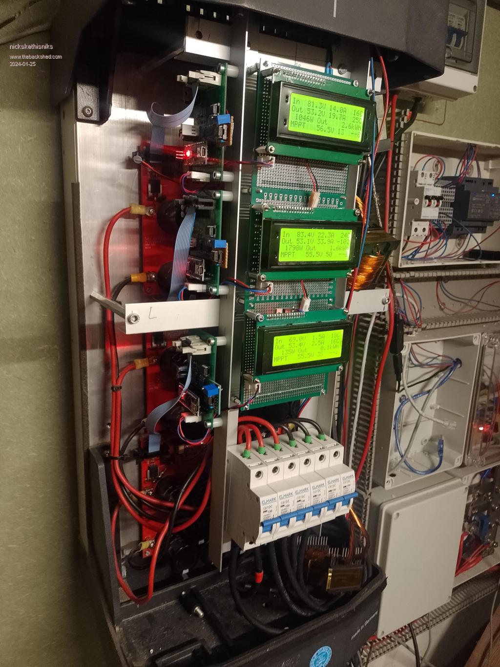 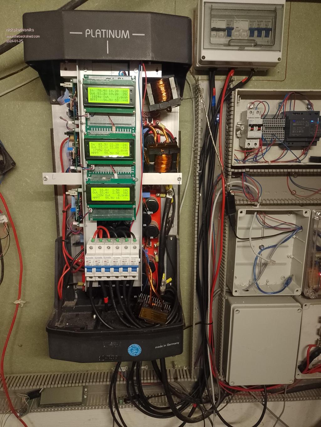 The power output is combined by 3 diodes wich are optional and increase the losses a bit, but I'm feeling safer this way for now. Edited 2024-01-25 06:01 by nickskethisniks |
||||
| Page 1 of 2 |
|||||
