
|
|
Forum Index : Solar : home made dual axis solar tracker
| Author | Message | ||||
| Tinker Guru Joined: 07/11/2007 Location: AustraliaPosts: 1904 |
I do like a challenge with my project and I certainly got plenty with this one  . .
Its about time that I use some RE to power my house and today it was done. I opted to use a grid independent system with a modest 2 x 210W panel set up. To get the most out of my panels they were fitted to a part time solar tracker. The output from the inverter powers the house lights (all cf type)and a very efficient chest type drinks fridge which I made from an old upright fridge. By part time I mean its timer controlled, advancing the panel angle by 15 degrees every hour. The control circuit is all electro mechanical and consumes no (zero) standby power drain. The timer does have a constant power drain but I managed to modify a commercial digital timer for a very low power drain (~0.15W). The all up power draw of the whole contraption is around 1.5KWh per year, something this tracker should easily recover in one day. Anyway, below are a couple of pictures of the tracker and its control panel in the shed. The tracker is up on the shed roof which slopes by 2 degrees from N to S. If anybody is interested in more details of this tracker please let me know, I have some more construction pictures. 

Klaus |
||||
| davef Guru Joined: 14/05/2006 Location: New ZealandPosts: 499 |
A couple of photos showing the detail of the 2nd axis would be helpful. It looks like you raise and lower the back end of the panel assembly. Like the idea of advancing the panel every 15 minutes rather than trying to track the sun. What is the drive motor? Nice job! Dave |
||||
| Tinker Guru Joined: 07/11/2007 Location: AustraliaPosts: 1904 |
Thanks Dave. The tracker advances the panel every hour, not 15 mins. Hourly intervals are really good enough IMO, besides there is a limit of timing intervals on the digital timers. Regarding timers, yes, the mechanical 240V timers have 15min intervals around the clock but I found these types rather poor time keepers. Also, the tracking motors only run for seconds so applying power to the circuit for 15 min is not desired. The circuit is self resetting, the timer supplies 12V for 1 minute to the motor control, that's all, no other control wires are used. The azimuth drive uses a windscreen wiper motor (55:1 worm gear), driving another 50:1 worm gearbox which has the solar panel shaft on its output. The declination drive uses a little 12V geared (50:1) motor from Jaycar, which drives a home made 82:1 wormgear, turning the spindle made up from lengths of allthread. Declination drive pics: 


The 'calibration stick' in the last picture lets me adjust for the day of the year, the drive motor has a quick connect link to stop it to adjust for leap years and other adjustments. Klaus |
||||
| davef Guru Joined: 14/05/2006 Location: New ZealandPosts: 499 |
Thanks for those pictures. An impressive job! I assume it is on a polar (?) mount so that the 2nd axis is only adjusted every few weeks or so. I was originally just going to use a single axis polar (?) mount and adjust the 2nd axis manually. However, the panels are now going to be mounted in a more inaccessible place . . . so, back to thinking about something like yours. Have you got a picture of the inside of the 1st axis drive 
Thanks, Dave |
||||
herbnz Senior Member Joined: 18/02/2007 Location: New ZealandPosts: 258 |
Hi A previous link that Glen started a clever solar tracher I posted some pics here it works great has for years uses old car diff both axis change as it swings round. I use a stick at right angles to check angle when setting. if no shadow its perfect but quite tolerent to some degree of error linl herehere |
||||
| GWatPE Senior Member Joined: 01/09/2006 Location: AustraliaPosts: 2127 |
Hi tinker, a nice piece of fabrication. I see no end of day reset, I assume the panel is returned to the morning position at the end of the solar day, with some index/limit positions. Gordon become more energy aware |
||||
| daveames Newbie Joined: 19/09/2009 Location: United StatesPosts: 30 |
hi tinker and the group, what a beautiful piece of work you have there. i have seen some absolute masterpieces on this board and this is another one. this post really caught my eye because just this morning i finished the initial beta model testing on a timer based tracker i knocked up- remarkably simular to yours! only a single though and nowhere near the craftsmanship of yours. aimed as a diy for us mere mortals. thanks soo much for sharing this beauty.. herb, had a look at that indestructilbe machine of yours! that baby will still be running long after we are gone! nice. kind regards, dave kb1mzf |
||||
| Tinker Guru Joined: 07/11/2007 Location: AustraliaPosts: 1904 |
Thanks for the compliments guys, I appreciate it. Here is a brief description how the device works: In the shed, below the tracker is the modified digital timer which turns a 240V relay on for 1 minute (its shortest interval) at each time slot set. The relay connects the tracker control & motors to 12V (tapped from one battery) for one minute only, no other electronics is used. Up in the tracker pivot box is this gear arrangement: 
The motor drive relays (simple H bridge) are in the little plastic box, the timing disk: 
can be seen in on the back of the gearbox. I also include part of the circuit, lets see who can figure out how it works .
BTW, this picture shows the timing disk at 11:30AM and also where it is during the night. Timing is this way: The panels spend all night horizontal. Just before 6AM 3 timing sequences turn it facing east at 45 degrees. It remains this way until 9:30AM when it starts tracking, moving by 15 degrees after each hour. By 2:30 it faces 45 degrees to the west and remains that way until 6PM, when it turns horizontal after 3 quick timing sequences. The lot is a fully automatic, non power hungry simple electro mechanical system. Its a compromise, I know, but better than a fixed panel. I was limited by the timer to 12 timing programs and 6 hour tracking, for 60 to 60 degrees and 8 hour tracking I would need a 16 timing program timer which I have never seen in the digital variety. 8 hour tracking is doable with this design but would be the max, for me the 7 notch timing disk was complex enough. Now to Dave's question, I originally had planned to adjust the second axis manually but the challenge to do it automatically proved irresistible once I realized that I already had the timing available. What happens is this: Each time the panel moves by 15 degrees the second axis spindle turns by 90 degrees. So, in 24 hours this spindle does 3 complete turns which, multiplied by the pitch of the thread (0.1") equals the required setting for the next day. Simple really, isn't it?
I really would be surprised if anybody comes up with a simpler two axis tracker that takes as little power as mine to run. I made a motor driven cam to replace the timer for accelerated testing and ran the thing for two years worth of tracking in the shed, it still takes about 3 days do do 6 months tracking with this. The unit performed flawlessly. But to be fair, I only installed it on the weekend and there may be some bugs when it runs on the roof. One I already found which has to do with the slight backlash of the worm gear box that drives the panel support tube. Since the timing disk is also directly connected to the gearbox output shaft it can also slightly wiggle when the wind plays on the panels. If this happens at the instant the panel moves, the hour micro switch (center one) might do a false trigger and advance the an extra 15 degrees. It happened once and my cure will be to install gas struts (like a steering damper) to the panel tube. This only turns through 90 degrees so installing the struts should do the trick. I happen to have this gearbox on hand, waiting for a use for years . I could have made my own, backlash free, worm drive - like the second axis one - had I known about this beforehand. Klaus |
||||
| daveames Newbie Joined: 19/09/2009 Location: United StatesPosts: 30 |
Hi Klaus, my jaw droped when i saw your "timing disk" wow! 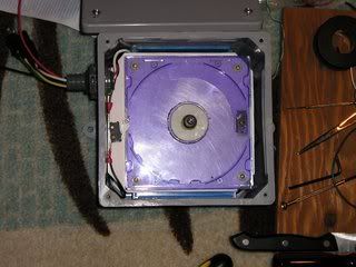
this is that prototype we worked up and tested. looks like we both got hit with the same bolt of lightning. cheers, dave |
||||
| davef Guru Joined: 14/05/2006 Location: New ZealandPosts: 499 |
Klaus, Thanks for the added information and picture. I'll have to keep my eye open for a gearbox similar to yours! Cheers, Dave |
||||
| Tinker Guru Joined: 07/11/2007 Location: AustraliaPosts: 1904 |
Dave, try to get a gearbox with minimal backlash or you might have to do this as well: 
The gearbox is a 'Reynolds' brand, fractional HP size, input shaft 12mm, output shaft 16mm diameter. Also look for a tapered roller bearing (I used an used one off my Landcruiser) to take the thrust load off the gearbox. It just needs to be beefy and in reasonable nick, the thing only turns 15 degrees every hour after all. Klaus |
||||
