
|
|
Forum Index : Other Stuff : Lead Batteries
| Page 1 of 2 |
|||||
| Author | Message | ||||
Bryan1 Guru Joined: 22/02/2006 Location: AustraliaPosts: 1206 |
G'Day Guy's, Firstly I'm starting this thread so my trials with lead batteries can be fully explored. Clockmans thread is about making a plante battery and now I'm on board playing with with this topic I do think it's best to start a new thread. With that out of way it's time to start  Ok for a bit of fun I made a single cell battery making 2 plates 170x270mm and used some 1/4" lead wire to go around the lead plate to support the plates and provide the connections. For the electrolyte i used a pool floculant with a ph of 3, now i have converted old N70 batteries using this and they just keeping on. To form these conversions first we have to use baking soda so we can neutralize the acid. Do this until when the baking soda doesn't produce bubbles which will prove the acid is totally gone. Then wash out several times to get all the baking soda and add a concentrated solution of the pool flocuent. I just left the batteries with 20 watts of solar for 2 months where i found the voltage was 16 volts. So i put the battery in my tractor and it started it on the first kick. I now use the 2 batteries I converted to power the fan on my listeriod and after 4 hours of running they go down to 9 volts under load and when the load is removed they go backup to 14 volts. So to finish this converting old N70 batteries are a good option as they only last 5 years and with this conversion another 5 or more years can be had. So back to this single cell battery this morning I drained the batteries then took them out and washed them in rain water and left them in the sun to dry. Well when I reassembled the battery using 34% sulphuric acid I put so i put that my meter across and found a voltage and when I put the reduction motor across it worked down to 0.4 volts. so I put a length of nichrome wire across and found the volt meter did get down to zero volts took the wire and found the voltage went back up to 1.1 volts.So with the new electrolyte added I'll leave it for a week to just see what voltage it gets to as this single cell is saying it has life. Now to think about this on serious note. By forming cells in a mold to suit a certain size is matter of making a mold and using a pre heat so the lead flows to through the whole mold. This would be an easy job on my cnc and hopefully a fixed 32 bit computer will turn up then the fun can begin. Add your thought about this topic here Cheers Bryan |
||||
| Godoh Guru Joined: 26/09/2020 Location: AustraliaPosts: 378 |
Hi Bryan, just wondering if you have checked to see what ampere hour capacity the rebuilt batteries are? Sounds like quite a bit of work to pull N70s apart and rebuild them. Are you replacing the plates inside with home made plates? Or are you just replacing the electrolyte. Pete |
||||
| Clockmanfr Guru Joined: 23/10/2015 Location: FrancePosts: 427 |
Bryan, Have a look at this utube vid from India. These vids are posted by a Indian guy that odes franchise business for ordinary folk across India to set up a business repairing/refurbishing commercially made old/used and shagged Lead acid 12v batteries. If you search he also shows the lead plate matrix casting, and the guy sat on the floor doing washing and rebuilding batteries. Very obviously personal protection and safety is not a major concern, Bloody hell!!!! https://www.youtube.com/watch?v=5BG8N0emfYE Everything is possible, just give me time. 3 HughP's 3.7m Wind T's (14 years). 5kW PV on 3 Trackers, (10 yrs). 21kW PV AC coupled SH GTI's. OzInverter created Grid. 1300ah 48v. |
||||
| Clockmanfr Guru Joined: 23/10/2015 Location: FrancePosts: 427 |
Bryan, There are a lot of things happening. Firstly, with a anode plate and a cathode plate, ie one lead plate and another plate facing each other this is called a single cell, the usable voltage of this cell will not exceed more than 2.3 volts, in practice its about 2.22volts. Secondly, on bare lead when you first fill with acid solution the cell becomes live, the acid solution is fully charged ie, its specific gravity is up at the appropriate levels this will change as the cell is discharged. Normally its about 1.265 and during discharge it will drop to about 1.150 and the electrolyte will only be 17%. When recharged the battery will rise again to 36% electrolyte and about 1.265 again. As the battery gets old in normal batteries, the specific gravity will drop as the internal plates deteriorate and the useful amp hour rates also drop. For our PLANTE its the other way around. Our initial Amp Hour rate is not as good as a modern commercial battery, ie only about 1/3rd but over the many years it will be used the battery gets better until eventually all the lead plates internally are just a oxide paste. So we need to hold that oxide as long as we can, and not allow it to short out the cell within the battery itself. Thirdly, when first filled you will see that the Cell is Bi- sexual, ie put your voltmeter leads on each plate, then remove the leads and swap them around and hay presto it gives voltage the other way around as well. Okay so we need to form the correct oxides to form on the correct plates. So to form we charge at 20% to 23% voltage of the 2.3 volt cell and at 10% to 13% of the rated Amp hour capacity of that cell. 12 volt batteries are normally 6off 2.22v voltage cells with each 2.22v cell have about 7off 2,22v cells parallel connected to get the Amperage out put up of each of the 2.22 cells in the 12v battery. Rated Amp hour capacity of your 2.22v cell for a PLANTE battery is defined roughly by surface area of each POSITIVE plate in that cell. So for your plates of 270mm x 180mm and at say 2mm thick, we need to know the plate weight to get the surface area that we can form to get the amp hour. however a rough guide for your plates of one cell would be very approx. about, 9amp hour for a kg of your size. Everything is possible, just give me time. 3 HughP's 3.7m Wind T's (14 years). 5kW PV on 3 Trackers, (10 yrs). 21kW PV AC coupled SH GTI's. OzInverter created Grid. 1300ah 48v. |
||||
| wiseguy Guru Joined: 21/06/2018 Location: AustraliaPosts: 993 |
Sorry - a bit off topic...... In a previous life I visited India to repair a solid state xray fluorescence detector. It measured the remaining metal content at the tailings of the slurry to determine whether to increase addition of expensive reagent to recover more metal. I visited the Lead concentrate section and I saw a worker carrying a hessian bag over his shoulder that had damp lead concentrate that had been shovelled into it, to the stockpile. He did this all day every day and he was chromed from head to foot apart from two brown eyes and glistened in the sunlight so it hurt your eyes. Even his loin cloth was chromed - all with lead concentrate. If I find the photo I'll post it later, unbelieveable ! I will restate clockmans comment "Very obviously personal protection and safety is not a major concern, Bloody hell!!!!" Edited 2022-01-10 09:08 by wiseguy If at first you dont succeed, I suggest you avoid sky diving.... Cheers Mike |
||||
| Warpspeed Guru Joined: 09/08/2007 Location: AustraliaPosts: 4406 |
Here is a different video from India showing what appears to be the exact same process: https://www.youtube.com/watch?v=XWi73Fee5J8 The dust, fumes, and smell must be incredibly bad. What is it they burn ? looks like composted wood chips ?? Cheers, �Tony. |
||||
| Clockmanfr Guru Joined: 23/10/2015 Location: FrancePosts: 427 |
Okay guys, got the Chargeing the PLANTE battery rates slightly wrong sorry about that. CHARGING the PLANTE battery. Okay so we need to form the correct oxides to form on the correct plates. So to form correctly for the best attributes for the oxide, we charge at 20% to 23% over the designated, designated voltage for each of our cells is 1.5v volt cell. And at 10% to 13% of the amperage of the calculated rated Amp hour capacity of that cell. So for a single cell designated 1.5volts your battery we need a charge at 2.43volts and at 0.92amps. Remember change the polarity for each of the 30 plus charges as you form the plates. Discharge rates for PLANTE battery plate oxide forming. Each of the 30 times minimum charge and discharge should be the same rates to form the correct Oxide. And remember the polarity should be reversed on each charge. On the 31st charge you will then make the positive palates positive from then on. Discharge should be about 10% of the cell capacity in voltage and amperage. So for your single cell, discharge it at about 2.442volts and at about 0.9amps. Edited 2022-01-10 19:57 by Clockmanfr Everything is possible, just give me time. 3 HughP's 3.7m Wind T's (14 years). 5kW PV on 3 Trackers, (10 yrs). 21kW PV AC coupled SH GTI's. OzInverter created Grid. 1300ah 48v. |
||||
| Warpspeed Guru Joined: 09/08/2007 Location: AustraliaPosts: 4406 |
To do this correctly thirty times requires a patience and a persistence that I simply lack. Bad enough trying to educate one single dumb cell thirty times, to do a whole battery can only lead to complete psychosis. And there are no short cuts to the long drawn out process. I think I would prefer to put my effort into building a clever circuit to do all this automatically. Should not be too difficult as its simple repetition. Something that measures the cell voltage, then stops charging at some point, does a full discharge down to some minimum voltage, does a swift gender change, and off it goes again in the opposite direction. A nice little project for either the software geeks, or the hardware circuit design guys. Cheers, �Tony. |
||||
| Davo99 Guru Joined: 03/06/2019 Location: AustraliaPosts: 1577 |
That's what I was thinking. For the use it would get and the time saving as well as I imagine the accuracy that could be built in, would seem to be a very worthwhile project. |
||||
| Bryan1 Guru Joined: 22/02/2006 Location: AustraliaPosts: 1206 |
G'Day Guy's, Just been upto the shed to check on the single cell and with no sun on the solar 2.32 volts. So took off one lead and left it for a few minutes for the resting voltage to stabilize and 2.06 volts. So I do think the sulphuric acid has made a huge difference, in 2 days with only 10 watts of solar which is only around 1.2 amps at best. To discharge the cell on Sunday I use about a metre of nichrome wire and sure enough it did go down to zero volts and stay there but as soon as the wire was removed it jumped backup to 1.5 volts. I will make a simple voltage doubler so I can use led's to discharge and the big 10mm ones I have do have a forward voltage of 3.2 volts so that doubler will be enough to get the led's to light then to finish off the discharge the nichrome wire will be used. I still need to source some MEK for making a bigger container so I can put more cells in to make a 12 volt battery then the main test will be my shed radio which I leave on 24/7. All good fun Cheers Bryan |
||||
| Clockmanfr Guru Joined: 23/10/2015 Location: FrancePosts: 427 |
Yes the Oxide forming does seem long winded. However what i understand is that its possible to do 6 cells at a time to make up a 12v batterycharging regime, but i have not tested this as of yet. Warpspeed, I am very interested in a little circuit, very interested indeed. My figures i posted for charge and discharge are correct for a single cell, designated as 1.5v. However, for my batteries at 550ah thats some charge rates at 55 plus amps. But i feel sure you can come up with a work around. Everything is possible, just give me time. 3 HughP's 3.7m Wind T's (14 years). 5kW PV on 3 Trackers, (10 yrs). 21kW PV AC coupled SH GTI's. OzInverter created Grid. 1300ah 48v. |
||||
| Warpspeed Guru Joined: 09/08/2007 Location: AustraliaPosts: 4406 |
O/k Leslie, first part of the puzzle, a battery cell sex changer that swaps the cell around so we are always dealing with the positive end with respect to ground. 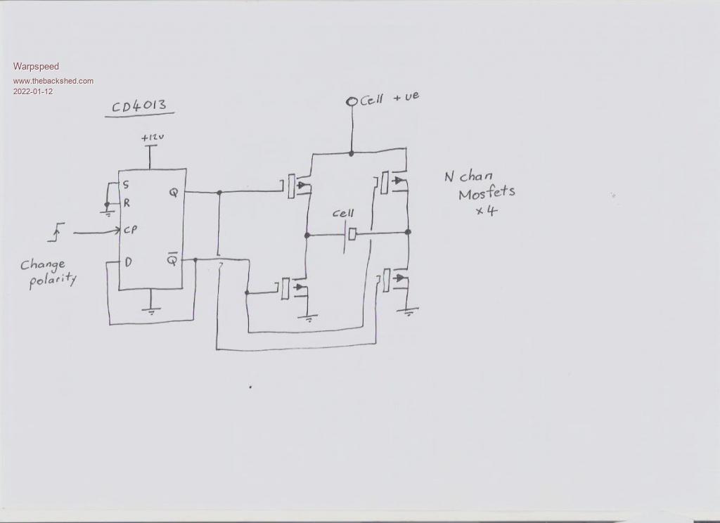 Its just a simple bridge circuit with four N channel mosfets. The mosfets can be as large and as many as necessary (perhaps with heatsinks), or really small for initial testing. As the "cell" will always be at less than 2.5 volts, if we drive the mosfet gates with a much higher voltage such as +12v, we can connect all our gates directly to a flip flop which really simplifies things a lot. The flip flop determines which end of the cell is grounded, and which end becomes positive, for the purposes of both charging and discharging. The next part consists of a stable 2.5 volt regulator using a TL431, and two potentiometers to set the max charging voltage and minimum discharge voltage. A multimeter direct onto the pot would be used to set the required voltages. 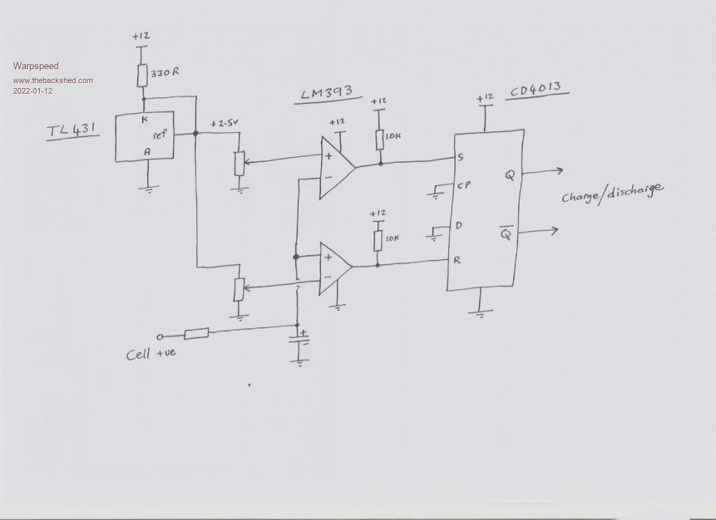 A couple of voltage comparators toggle another flip flop to either the "Charge" or "discharge" mode. The discharge load could be a simple resistor or something a bit more complex such as a constant current load. Charging circuit can also be simple or complex. The charge/discharge flip flop just cycles back and forth between the two set voltages. That can toggle the sex change flip flop so it goes through a charge discharge cycle, then changes sex before going through the next charge discharge cycle. Its not a complete circuit, but just a concept. I think something quite simple would be well up to the job. A digital or electromagnetic counter could count the number of sex change cycles easily enough to know when you get to thirty, or whatever. Cheers, �Tony. |
||||
| Warpspeed Guru Joined: 09/08/2007 Location: AustraliaPosts: 4406 |
Thinking about a discharge load. The problem with a resistor, is that as the voltage falls, the current falls too, so discharge times can be very long if you want go down to a really low final discharge voltage. One simple solution would be to use filament lamps as a discharge load. The hot resistance of the lamp at full brightness will be ten to fifteen times higher than the stone cold resistance of the filament. So as the battery discharges, the discharge current falls off, but not as quickly as with a plain fixed resistor. Also lamp brightness is a pretty good indication of how discharge is going. Just had a look at a 230v light globe that says on it 77 watts. Hot resistance should therefore be about 230 x 230 / 77 = 687 ohms. My multimeter says the cold resistance is 51.8 ohms. Therefore hot resistance is x13.2 Tried a stop/turn indicator bulb. It says on it 12v 23 watts. Hot resistance maybe 12 x 12 / 23 = 6.26 ohms. Multimeter says about 0.5 ohms cold. Hot resistance x 12.5 It might be difficult finding 2.5 volt rated bulbs though, although you used to be able to get flashlights that used a couple of 1.5v D size dry cells. I guess its all leds these days, but the bulbs may still be available. Cheers, �Tony. |
||||
| Clockmanfr Guru Joined: 23/10/2015 Location: FrancePosts: 427 |
Tony, I had a good chuckle when i read your "the sex change" comment. That looks a nice simple circuit. Discharge load is an issue, but we definitely do not want to exceed the discharge rates i have given. And yes other info i have and seen on discharge systems for smallish PLANTE batteries has been filament light bulbs, and as you say you can see the light slowly diminish. However, as the oxide builds up then the PLANTE battery starts to give a better holding voltage, so charge rates stay the same but the time required may get longer, and the same with the discharge cycles. At present i have no exact data on the differential time's required between each cycle, or your phrase 'sex change' as the correct plate coating oxide builds up. Somewhere on those Indian Utub vids there is one showing a small indian building with banks of resistors and chargers, for starting BIG normal lead matrix and paste filled plate batteries. Everything is possible, just give me time. 3 HughP's 3.7m Wind T's (14 years). 5kW PV on 3 Trackers, (10 yrs). 21kW PV AC coupled SH GTI's. OzInverter created Grid. 1300ah 48v. |
||||
| Warpspeed Guru Joined: 09/08/2007 Location: AustraliaPosts: 4406 |
One thing to note about the sex change circuit. You must discharge the cell to less than 0.5 volts before inverting the polarity, if you don't the inverse diodes in the mosfets might be a problem. Also when reconnecting a fully charged cell, it must go in the right way around or once again there might be a problem diode right across the cell that causes a high uncontrolled discharge current. A simple fix would be to fit a couple of red leds connected to the flip flop to show which cell terminal is currently the (safe) positive side. A constant current cell discharger is pretty easy to make, its only a few components if its going to make all this a lot easier. Edited 2022-01-15 14:46 by Warpspeed Cheers, �Tony. |
||||
| Bryan1 Guru Joined: 22/02/2006 Location: AustraliaPosts: 1206 |
G'Day Guy's, Checked the single cell this morning and with no solar input 2.33 volts so decided to drain the battery so connected that reduction motor and left it running. Came backup to the shed after lunch and that motor was still going and the voltage was down to 1.4 volts so put on the nichrome wire and about an hour later it was down to 0.5 volts. As the sun was about to shine thru the shed door changed the polarity and put my dmm on where on the 20 volt setting it was showing zero volts so put it on the 2 volt setting and 0.005 volts. Take off the solar and it jumps to -0.7 volts so it is going to take a few days for the polarity change to really take effect. As a precaution using the sulphuric acid I put the cell in a square bucket and noticed today some liquid in the bottom of the bucket, tested with some ph papers and it is acid. now the liquid level I set was about 15mm above the plates and it had dropped to the top of the plates so it is only a very small leak and not a problem yet. All good fun Cheers Bryan |
||||
| InPhase Senior Member Joined: 15/12/2020 Location: United StatesPosts: 178 |
So, why do we need to discharge the battery through a load before applying the reverse voltage? Wouldn't switching charge polarity and the resulting reversal of current effectively be the same thing? In my mind, when the polarity is reversed, it is the same as putting the cell(s) in series with the power supply and shorting the ends. The FETs of the bridge would dissipate heat just like a load. No? |
||||
| Warpspeed Guru Joined: 09/08/2007 Location: AustraliaPosts: 4406 |
I suppose it depends if you are paying for the power. Costs nothing to heat up a resistor. If you are sucking power from the grid to discharge your cell, it ain't free. Cheers, �Tony. |
||||
| Bryan1 Guru Joined: 22/02/2006 Location: AustraliaPosts: 1206 |
Inphase I've been living off the grid now for 20 years and this attempt at making a battery is inspired by Clockman and his project. My whole project came together in less than an hour which was finding the lead sheet and my old etching tank. Untangling the 1/4" lead rope to put around the lead sheet to make it more stable and mixing up some pool flocculant then simply putting 2off 5 watt solar panels on it to charge it. After a couple of weeks I changed to acid and if you go and read Clockmans details on making abattery you will learn by discharging the cell first is the key. As the lead plates naturally hold a voltage it did take a couple of hours under charge for the voltage to reverse and on looking last Sunday they are back to 2.56 volts with the solar disconnected. So this weekend the smae thing will happen, put my reduction motor and nichrome wire on as a load and leave it until under 0.4 volts is left. Then just before the sun hits the panels reverse the connectors and this will complete one full cycle. I do have a lead sheet 450x900mm so I do need to workout what measurements to cut so I can make a 12 volt battery as the end goal is a battery replacement for my old Nife nicad batteries that are now more than likely over 50 years old and are too tired to run my shed radio 24/7. To charge this 12 volt battery will be a 20+ year old 80 watt solar panel that still puts out the rated current so doing a bit more research and logging the dimensions, weight etc we can then workout the AH rating. All good fun Cheers Bryan |
||||
| InPhase Senior Member Joined: 15/12/2020 Location: United StatesPosts: 178 |
I'm a little dense, so bear with me... Isn't it the same thing? The total amount of energy is the same whether you discharge through a load or if you reverse the polarity against the charged cell. Scenario 1): Put 10 joules into a cell. Disconnect power. Discharge 10 joules from cell. Apply reverse current. Put 10 joules into cell. Total energy from supply = 20 joules. Scenario 2) Put 10 joules into cell. Reverse current. Current is doubled because cell and power supply are in series. 10 joules dissipated as heat in FETs. 10 joules absorbed by cell. Total energy = 20 joules. |
||||
| Page 1 of 2 |
|||||
