
|
|
Forum Index : Microcontroller and PC projects : OLED Question
| Author | Message | ||||
| Frank N. Furter Guru Joined: 28/05/2012 Location: GermanyPosts: 818 |
Hi all, I bought a OLED on Ebay. It looks very similar to this one and has the same pin-description: 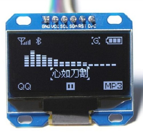
My question is now: Is it configured als SPI or IIC???? It has no soldering Jumpers on the other side and I can't find any information about the configuration... It should be possible to use this OLED as SPI OR IIC device but what must I do??? 
(I would prefer SPI...) Thanks for any help!!! Frank |
||||
| plasma Guru Joined: 08/04/2012 Location: GermanyPosts: 437 |
i mean its I2c. dont forget the resistors ,load the forum code this need 2-3 minutes and you know it . |
||||
| Frank N. Furter Guru Joined: 28/05/2012 Location: GermanyPosts: 818 |
Hi Plasma, thanks for your answer - but what shall I do with RST and D/C??? Shall I leave it open? Frank |
||||
| plasma Guru Joined: 08/04/2012 Location: GermanyPosts: 437 |
maybe this help , http://smart-prototyping.com/OLED-0.96inch-12864-display-mod ule-blue.html looks like it support spi and i2c , dc switch the mode (?) and reset is reset . i dunno really but beware the 5v using , my device uses only 3,3 v and works fine with i2c |
||||
Justplayin Guru Joined: 31/01/2014 Location: United StatesPosts: 313 |
D/C is for indicating if you will be sending it data or a command. --Curtis I am not a Mad Scientist... It makes me happy inventing new ways to take over the world!! |
||||
| matherp Guru Joined: 11/12/2012 Location: United KingdomPosts: 8645 |
Can you post a picture of the other side of the display? Try it with my I2C code in this thread. It won't do any harm and may work - let me know. I suspect it will default to SPI but there needs to be a CS connection as well. Looking at pictures of various versions on ebay it looks like there may be an option to permanently connect CS. Given a picture I may be able to help This is the pinout for the ribbon from the display. BS0-BS2 select the interface type according to this: I2C Interface 0,1,0 4-wire Serial 0,0,0 3-wire Serial 1,0,0 Pin No. Pin Name Description 1 NC(GND) Reserved pin. It should be connected to VSS. 2 C2P 3 C2N C2P/C2N � Pin for charge pump capacitor; Connect to each other with a capacitor. 4 C1P 5 C1N C1P/C1N � Pin for charge pump capacitor; Connect to each other with a capacitor. 6 VBAT Power supply for charge pump regulator circuit. 7 NC No connection. 8 VSS Ground pin. 9 VDD Power supply pin for core logic operation. 10 BS0 11 BS1 12 BS2 MCU bus interface selection pins. 13 CS# This pin is the chip select input connecting to the MCU. 14 RES# This pin is reset signal input. 15 D/C# This pin is Data/Command control pin connecting to the MCU. 16 R/W# This pin is read / write control input pin connecting to the MCU interface. 8080: data write enable pin; 6800:Read/Write select pin. When serial or I2 C interface is selected, this pin must be connected to VSS. 17 E/RD# 8080: data read enable pin; 6800:Read/Write enable pin. When serial or I2 C interface is selected, this pin must be connected to VSS. 18 D0 19 D1 20 D2 21 D3 22 D4 23 D5 24 D6 25 D7 These pins are bi-directional data bus connecting to the MCU data bus. When serial interface mode is selected, D0 will be the serial clock input: SCLK; D1 will be the serial data input: SDIN and D2 should be kept NC. When I2 C mode is selected, D2, D1 should be tied together and serve as SDAout, SDAin in application and D0 is the serial clock input, SCL. 26 IREF This pin is the segment output current reference pin. A resistor should be connected between this pin and VSS. 27 VCOMH COM signal deselected voltage level. A capacitor should be connected between this pin and VSS. 28 VCC Power supply for panel driving voltage. 29 VLSS Ground pin. 30 NC(GND) Reserved pin. It should be connected to VSS. |
||||
| Justplayin Guru Joined: 31/01/2014 Location: United StatesPosts: 313 |
This ebay listing appears some info that may help. OLED LCD LED Display Screen Module SPI IIC I2C --Curtis I am not a Mad Scientist... It makes me happy inventing new ways to take over the world!! |
||||
| Frank N. Furter Guru Joined: 28/05/2012 Location: GermanyPosts: 818 |
Thanks a lot for yours help! Please excuse me for my long absence! I have at the moment problems to flash my 32MX170 (28pin) controller. I have the very stupid Microstick II which only is supported from MPLAB IDE and NOT from MPLAB X. ...but MPLAB IDE supports only 32MX150 and not the 32MX170 and MPLAB X doesn't support my Microstick II as Programmer  
Now I must build an adapter to use my PICKIT3 clone... I will post again when I have a working Micromite with 32MX170. (all MKII what I have built in the past was 44pin �Mites in my Job) Frank |
||||
| plasma Guru Joined: 08/04/2012 Location: GermanyPosts: 437 |
ich brenn sie wenn du m�chtest! i have a pickit3 , if you need help! |
||||
| Frank N. Furter Guru Joined: 28/05/2012 Location: GermanyPosts: 818 |
Vielen Dank! Thank you very much! I have a pickit3 (clone) too - but I have to built an adapter for it (...and I have at the moment absolutely no time )
Thanks again!!! Frank |
||||
| Frank N. Furter Guru Joined: 28/05/2012 Location: GermanyPosts: 818 |
Ok, I have a PIC 32MX170 (28 pin) as Micromite with MKII V4.6a running but no luck with my OLED. GND - GND VCC - 3V SCL - Pin 17 with 10K pullup to 3V SDA - Pin 18 with 10K pullup to 3V Running OLED-ssd1306-i2c.bas from 2015-01-18_190412_Graphics-v1.2.zip: Darkness as in a moonless night... 
...what shall I do with RST and D/C? Can anybody help me? THANKS!!! Frank |
||||
| Justplayin Guru Joined: 31/01/2014 Location: United StatesPosts: 313 |
I have not played with any of the new graphic libraries which have been posted, but when I have toyed with the Nokia 5110 dispalys. On the Nokia display the RST is the reset line and needs to be wired to a pin on the Micromite and is toggled during the initialization of the display. The D/C is the Data/Command line and is toggled to indicate the bytes next sent to display will either be data or a command. So, D/C will also need to be wired to a pin on the Micromite. --Curtis I am not a Mad Scientist... It makes me happy inventing new ways to take over the world!! |
||||
TassyJim Guru Joined: 07/08/2011 Location: AustraliaPosts: 5949 |
I think that D/C is only used for SPI. Most of the modules can be configured for either I2C or SPI. Can you rty the SPI code? Jim VK7JH MMedit MMBasic Help |
||||
| Frank N. Furter Guru Joined: 28/05/2012 Location: GermanyPosts: 818 |
It's alive!!! [ 
I connected it as SPI and tried Matherps SPI version! I bought it as a blue OLED display but it is a yellow/blue one like this one: 
The backside looks exactly like here: 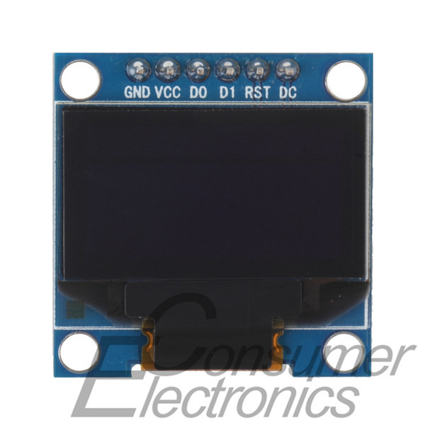
In the description of this display stand that this is a SPI device (I bought mine as I2C AND SPI...) but I am happy that it works!!! Many thanks to Matherp for his work and all the others for helping!!! Frank 
|
||||
