
|
|
Forum Index : Microcontroller and PC projects : Spa Controller
| Author | Message | ||||
| Tinine Guru Joined: 30/03/2016 Location: United KingdomPosts: 1646 |
Bill, the way I read it; the TX is only gating itself with the enable. Not totally sure why the delay is required, TBH...I will read again later. |
||||
| Tinine Guru Joined: 30/03/2016 Location: United KingdomPosts: 1646 |
FWIW:I always start my transmissions with AA (10101010). Regards, Craig |
||||
| Phil23 Guru Joined: 27/03/2016 Location: AustraliaPosts: 1664 |
Ended up finding 3 of the Auto switching modules in one of my parts drawers. Good thing is that I can directly swap one out for the HC-11 that is currently on Com1 of the heat pump controller, and not need to worry about changes to the board to accommodate the DE pin. Did also find a good data source on the module, including schematic here... https://protosupplies.com/product/scm-ttl-to-rs-485-interface-module/ Cheers. |
||||
| Turbo46 Guru Joined: 24/12/2017 Location: AustraliaPosts: 1593 |
Thanks for that Phil23. The circuit is similar to that posted by Tinine but the 27uS delay has been extended out to over 5mS! It looks like a good device, well protected and documented. Considering that I bought the MAX485 chip locally for $5.95 the price is good too. I have used one of these devices on my laptop to talk to RS485 devices using DOS MMBasic. It must use a similar automatic direction control. 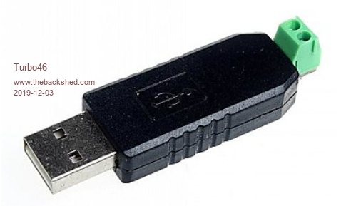 Bill Keep safe. Live long and prosper. |
||||
| Phil23 Guru Joined: 27/03/2016 Location: AustraliaPosts: 1664 |
Have the same USB one too. Found it very useful for monitoring the bus when I was setting up the coms between the MM & the Modbus meters. |
||||
| Phil23 Guru Joined: 27/03/2016 Location: AustraliaPosts: 1664 |
So 5 years down the track it's died. Relied too long on my Prototype hardware & never quite got to a soldered board. (Strip would do it). So in the interim I'm controlling the circulation pump with a smart switch via Home Assistant. Basically getting data, (Solar Energy, Air Temp & Water Temp) from an Ecowitt Weather Station that Home Assistant integrates with. Control & making the most of the Sun is very poor in comparison to my MM build, but I do like the data I can see in HA, as well as the presentation. Which gets me thinking. The Pico Pi W, that has popped up recently. Will it be offering anything interesting in the Micromite World? The thought of MQTT, which I know little about sounds like an opening to outside communications. Could scrap my who;e MM build, but think that's the wrong way to go. Coms to the outside world though would be a huge addition to the MM World. Cheers Phil |
||||
TassyJim Guru Joined: 07/08/2011 Location: AustraliaPosts: 5895 |
Hi Phil, No MMBasic for the pico W. PS. Your Lightning detector controller needs a firmware update. The GPS has suffered from a week 1024 rollover. Plenty of info on the Blitz forum. Don't get caught by blaming the GPS antenna before checking the forum (like i did). Jim Edited 2022-11-21 06:54 by TassyJim VK7JH MMedit MMBasic Help |
||||
bigmik Guru Joined: 20/06/2011 Location: AustraliaPosts: 2870 |
G�day All, @phil23, 2m will be a piece of cake with serial at 115200 baud. I tested it over 11m but others have successfully ran 50m See this thread >> Link << @tinine, With RS485 GND is not needed between the nodes, only the differential pair(s) Kind regards, Mick Mick's uMite Stuff can be found >>> HERE (Kindly hosted by Dontronics) <<< |
||||
| Phil23 Guru Joined: 27/03/2016 Location: AustraliaPosts: 1664 |
Thanks Jim, And Yes I was browsing down the road of a replacement GPS Receiver. Was blaming years in the weather for it's demise. Saw an upgrade was mentioned, but got Gun Shy of doing it while thinking I had a dead GPS. Didn't read on for specifics, but am aware the roll over has killed a few things. An Old Garmin eTrex & the GPS Speed Controller in my Boat. Boat Controller manages the throttle position & RPM & maintains Speed to timed 0.01 Seconds over a 16.08 Second run, with timing checked at 7 distance points along the way..... |
||||
| Mixtel90 Guru Joined: 05/10/2019 Location: United KingdomPosts: 5708 |
In theory, GND isn't needed for RS485... In actual fact you tend to get problems if it's omitted. It's quite true that the data is carried in the differential signal, but if both lines drift far enough away from GND you hit the common mode limit of the chips. At that point you start to lose either the "1"s or the "0"s as they can no longer be decoded. It can even cause damage in some cases. This is why, for long distance RS485, you need full diode and voltage protection at both ends. Over short distances, in reasonably electrically quiet conditions you'll usually get away without the GND (providing the transmitter and receiver are either galvanically isolated from each other in some way or their GND potentials are close). For long distances it's very unwise to run without GND and balancing resistors, as well as termination resistors. Mick Zilog Inside! nascom.info for Nascom & Gemini Preliminary MMBasic docs & my PCB designs |
||||
| bigmik Guru Joined: 20/06/2011 Location: AustraliaPosts: 2870 |
Hi Mick (the other one), When I was employed in the racing game we ran RS485 up-to 1500m. The server in the control room had mains earth connected to logic GND We ran 5 pair shielded CAT3 cable, on that cable shield was Mains GND, the 10 wires were Channel A Tx+ Tx- Rx+ Rx- Channel B Tx+ Tx- Rx+ Rx The other 2 wires were both connected at the servers (2 servers channel A and Channel B) GND and was passed through all of the daisy-chained data cabling infrastructure. However the terminal feed leads did not have these GNDs nor the shield connected from the infrastructure cables to the terminal so electrically only the dual differential wires were connected from the servers to the terminals. You could argue that the remote terminals (we had up to 16 on each line) picked up GND through the EARTHING point and you have a case I suppose. We often had data errors causing issues on the long runs so I designed an opto isolation box that removed all electrical continuity from its input to its output, it used a transformer with 2 secondary windings so input and output had totally isolated power supplies, this cleaned up the data loss and IMHO it proves that the data lines alone is all that is needed. Towards the end of my career we started to use unshielded cat 5 cable for the temporary runs could be a couple of hundred meters or more and these had no GND or Earth connections just the 8 differential lines. Now all of the above is on 4 wire RS485, I have no experience with 2 wire, perhaps this is different. Kind Regards, Mick Mick's uMite Stuff can be found >>> HERE (Kindly hosted by Dontronics) <<< |
||||
| Mixtel90 Guru Joined: 05/10/2019 Location: United KingdomPosts: 5708 |
Once you isolate with transformers or optocouplers the problem has gone. The driver side can float independently to the line side so will always stay within the common mode range. :) Mick Zilog Inside! nascom.info for Nascom & Gemini Preliminary MMBasic docs & my PCB designs |
||||
| bigmik Guru Joined: 20/06/2011 Location: AustraliaPosts: 2870 |
Mick, the opto isolator box was only used in extreme situations, I was meaning to point to the fact we used cat 5 with no grounds or earths over hundreds of metres. Anyway as per all of these things YMMV. Take care, Mick Mick's uMite Stuff can be found >>> HERE (Kindly hosted by Dontronics) <<< |
||||
| Phil23 Guru Joined: 27/03/2016 Location: AustraliaPosts: 1664 |
Thanks again @TassyJim Just updated it to 9.4. Haven't read all the treads about the issue, but it now has a lock, just not showing a correct date & assume the time is GMT. Is the firmware in the actual GPS Receiver able to be updated too. Assume that's where the root of the issue lies. Not sure how that would be done with this type of device that communicates over a single Coax feed. 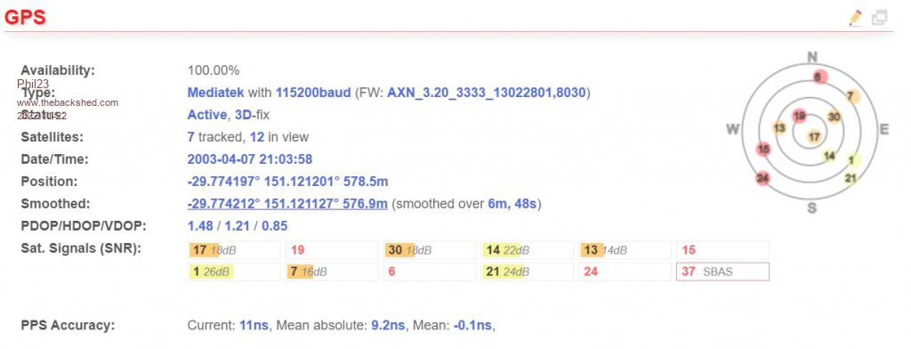 Also just read the intro of Peter's post Re the PicoW firmware. Last 3 years have had a lot of turmoil & little time to play with devices, but hopefully settling back to normal over the next six months. Cheers. |
||||
| TassyJim Guru Joined: 07/08/2011 Location: AustraliaPosts: 5895 |
If you don't use the blitz as a NTP server, you don't have to worry about the date being out. The time is correct. If you do want to use the Blitz as an NTP server like I do, you have to update the GPS firmware. The full instructions are on the forum but a simple todo: You power the Blitz from your PC so you can use the USB to serial built in to the unit. You also need TCPIP access. You have to install some STM drivers. If your PC has been used for a few other STM chips, you may have the driver already. The W8 driver works for W10 and W11. Via the web interface, turn the USB port 'on' Run the PowerFlash from the globaltop zip Update to V3.8 and all will be well. A lot of users seem to have problems but a lot of users are not very PC savvy. GlobalTop FlashTool.zip stm32102.zip Jim VK7JH MMedit MMBasic Help |
||||
