
|
|
Forum Index : Microcontroller and PC projects : Problems using count on MM+ V5.2
| Author | Message | ||||
| AussieWombat Newbie Joined: 04/05/2018 Location: AustraliaPosts: 21 |
Hi all, I'm trying to use my MM+ to act as a RPM meter on my CNC spindle, as I only have a pot to adjust speed. The g-code S command doesn't work on my spindle. I am using an arduino hall effect module from Jaycar CAT.NO: XC4434. My MMBasic program: cls setpin 52,cin do for x=0 to 59 '60 seconds pause 1000 '1 second increments text 200,20,str$(x,4),LM,5,1 'display seconds in top corner of screen if x = 9 then 'display count after 10 seconds on 1 line GETA 'call sub to read pin 52 and assign to "a" text 10,20,str$(a,4),LM,5,1 ' display text on separate line. endif if x = 19 then ' display after 20 sec. GETA text 10,50,str$(a,4),LM,5,1 endif if x = 29 then ' display after 30 sec. GETA text 10,80,str$(a,4),LM,5,1 endif if x = 39 then ' display after 40 sec. GETA text 10,110,str$(a,4),LM,5,1 endif if x = 49 then ' display after 50 sec. GETA text 10,140,str$(a,4),LM,5,1 endif next x GETA print a text 160,170,str$(a,4),CM,5,1 ' display after 1 min. setpin 52,CIN ' reset count Loop ' do it again end sub GETA a=Pin(52) end sub I would assume, as the magnet goes around, that the led flashes, and my count for each 10 second report, would be very close to each other, but that is not the case. My spindle, from manufacturer has a maximum of 2500 rpm (yeah I know I need a faster spindle), but the program reports a maximum of between 4600 and 5000. If I slow the spindle down so I can count the flashes, it still reports 3000+. Even if I turn it off, sometimes the count keeps going up. If I move the sensor away so that the led doesn't flash, and rotate the spindle 1 turn by hand, it will count up to 4-20 pulses. If I run the spindle I end up with higher numbers. When I do a test on my desk, using a magnet, all works ok. Do I need a pulldown on pin 52, to stop errant signals? Any help would be appreciated. Tried to update firmware to 5.05.03 but my pickit3 refused to connect under MPLABS IPE 5.45 , running x64 Win10. Regards Aussiewombat Edited 2021-01-24 16:34 by AussieWombat |
||||
| Geoffg Guru Joined: 06/06/2011 Location: AustraliaPosts: 3165 |
Your code looks OK. That must be the clue, obviously you have noise or some other effect causing pin 52 to count pulses when the hall effect sensor is not outputting anything. Assuming that you mean MPLAB X IPE... that should work. Check here for clues. Geoff Geoff Graham - http://geoffg.net |
||||
| AussieWombat Newbie Joined: 04/05/2018 Location: AustraliaPosts: 21 |
Thanks Geoff, You Wrote: Yes, I did mean that, and I had already been to your page for clues. I selected the Pic32MX470F512H as the target chip, and connected the pins to the pickit3 that circuitgizmo had set on this page at the bottom. Should the led blink? When I supply the target with power, after all the connections are made to the MCLR, VCC, VDD, pin D9 and Pin D0, as there is no ICSP header. The pickit3 has all three led's lit at first, then the status led goes out. The IPE still recognises the pickit3, but fails to connect. I am connected to the rear USB port, not a hub. I just plugged the pickit3 into my computer with no pins connected, and the computer says the last device failed. In the device manager it says, device descriptor request failed. When unplugged, then re-plugged all is ok. regards Aussiewombat |
||||
| Geoffg Guru Joined: 06/06/2011 Location: AustraliaPosts: 3165 |
I have never figured out the LEDs on the PICKit 3 so I cannot help there. Fails to connect to what? The PICKit3 or the chip? What is the exact error message? Geoff Geoff Graham - http://geoffg.net |
||||
| AussieWombat Newbie Joined: 04/05/2018 Location: AustraliaPosts: 21 |
mplab x ipe finds pickit3 just won't connect to device 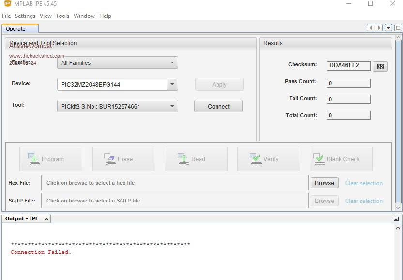 |
||||
| AussieWombat Newbie Joined: 04/05/2018 Location: AustraliaPosts: 21 |
gonna add a pulldown on signal line and try again tomorrow. Was working on V5.2 pic was from trying to update micromite extreme 144 Edited 2021-01-24 22:54 by AussieWombat |
||||
| Geoffg Guru Joined: 06/06/2011 Location: AustraliaPosts: 3165 |
It would be helpful to have the full output from IPE with the correct chip. Normally the error is "Target Vdd not detected" or "Cannot read device ID". Regardless, the PICKit3 and MPLAB X IPE do work perfectly on the CGMICROBOARD2 so it must be something you have wrong. It could be incorrect wiring, a load on PGD and/or PGC, a capacitor on MCLR, poor power on the target, etc. The list is endless and you will just have to start troubleshooting. Pulldowns (or pullups) on PGD or PGC are not needed and will probably introduce another source of errors. Geoff Geoff Graham - http://geoffg.net |
||||
| AussieWombat Newbie Joined: 04/05/2018 Location: AustraliaPosts: 21 |
I am going to post this in stages, as it says I have special characters like emoji's in it. I want to break it up so I can tell which section it is picking on. The picture I posted looked the same when I selected the PIC32MX470F512H as the target chip. I would probably agree. |
||||
| AussieWombat Newbie Joined: 04/05/2018 Location: AustraliaPosts: 21 |
The settings I used were on the bottom of the CGMICROBOARD2 Technical Info page I linked to before. Quoted from page:(It must have been a character in this quote that I copied from the page. Ok Once I re-typed it) I'm not sure on the capacitor, but the PSU is a 12V, 1.5A Transformer. I did not imply I was using a pulldown when using the Pickit3. What I meant was, I am going to try using a Pulldown on the signal line from the Hall effect sensor output to minimise errant signals. I will have to try and see what is going on with my pickit3. Should the led blink when in programming mode, and attached to pickit3, and power? This morning I added the pulldown to the Hall effect sensor, and it didn't seem to make any difference. The results were not consistent. I then decided to measured 3 times, without the magnet attached, and averaged the result, and then I added the magnet, and again averaged 3 results. I then subtracted the first non magnet readings, from the magnet readings. I also moved the sensor away from any magnetic metal, by placing a 10 mm diameter aluminium rod (100 mm long) into the chuck. I measured without a magnet and got 0 all round. I then added the magnet with some insulation tape and measured again. My results for non metallic: I will call them 1 (slowest) to 4 (fastest) 1: 119, 239, 361, 481, 600, 720 with an average gap of 120 2: 230, 457, 684, 911, 1138, 1366 avg. 227 3: 385, 776, 1167, 1557, 1947, 2337 avg. 390 4: 441, 873, 1316, 1753, 2191, 2631 avg. 438 My results for the first 10 seconds with a magnet minus without a magnet are: 1: 126 , 60 sec. 668 2: 225 , 60 sec. 1298 3: 369 , 60 sec. 2200 4: 424 , 60 sec. 2552 which sort of align with my non metallic results. Thankyou Geoff for assisting me in trying to nut this one out. Regards Aussiewombat Edited 2021-01-25 10:31 by AussieWombat |
||||
TassyJim Guru Joined: 07/08/2011 Location: AustraliaPosts: 5895 |
The Jaycar module isn't very helpful but I expect that the output is open collector. That means you will need a pull-up resistor, not pull-down. 4.7k should do nicely. You should be able to measure the output voltage with and without a magnet close and it should be high with no magnet and low with close magnet. You need to run the module on 5V but if your count pin is not 5V tolerant, putting the pull-up to 3.3V 'should' work. Jim VK7JH MMedit MMBasic Help |
||||
| AussieWombat Newbie Joined: 04/05/2018 Location: AustraliaPosts: 21 |
@ TassyJim I had chosen a 4K7 resistor but did use it as a pulldown. That is why I chose pin 52 on the MM+, it is a count pin that is 5V tolerant. That is why when I tried it on the MMX144, it didn't work, for as much as I could tell, none of the count pins were 5V tolerant. Peter Maher may correct me if I am wrong. When I ran the program on the MMX144, and used any of the count pins listed, 6,11,12 and 13. The only count I got was a one every time. I assume by the row of count pins being in the layout on the board, with a 3.3V supply and a ground. I was going to leave the device on the machine, but decided not to, as I hope to get a new 24K spindle with VFD to alleviate some of my issues with my CNC Router/mill. I hope to do this in the next month or so. That's when I decided to use the hall effect sensor for better things, and add some more homing limits, with my first one on my rotary axis(B), as A is slaved to X, working extremely efficiently. Better so than the microswitch I had earlier, which had the problem of wear and tear on touching parts, and not homing to the exact same spot, every time. I thank you for your advice, TassyJim, and if I had chosen to keep it, I would have tried that. Now at least I know roughly how fast my spindle currently goes in 4 positions, rather than just a maximum of 2500. Now if I can only work out what I am doing wrong with my pickit3. May have to contact CircuitGizmo for some advice. Regards Aussiewombat |
||||
Chopperp Guru Joined: 03/01/2018 Location: AustraliaPosts: 1032 |
Hi FWIIW, I use the Jaycar Hall effect module straight into an Armmite F4 (with no extra resistors) also in a Tacho circuit. The output should be high with no magnet (LED dim) & low with a magnet in range (LED bright). I found that the orientation and proximity of the magnet relative to the sensor was fairly critical to get consistent results. I use period input as I'm counting low RPM's from normally from about 20 to 200 RPM, but it will read up to over 2000 RPM. I use another input in parallel to trigger an interrupt routine which reads the value of the period for each pulse, then convert that to RPM. Fairly crude, but works OK. Brian ChopperP |
||||
| AussieWombat Newbie Joined: 04/05/2018 Location: AustraliaPosts: 21 |
I found the opposite. There is a slight voltage 0-800mV when there is no magnet(led dim), and 5V when the magnet in range(led lit). Once I apply the pulldown the voltage on the signal line drops to almost 0, and when magnet in range(led lit) about 4V. I was using a 4K7 resistor, but I assume a higher value would make the count more accurate. I have a better understanding of the speeds of my spindle with 4 calibration marks, rather than a ramp image on a pot., and feel I could use the hall effect sensors better, as a homing sensor with no contact, so shouldn't have any wear. Regards Aussiewombat P.S. I also got the updates to work between my Pickit3 and MM+, so everything now ok. |
||||
| Chopperp Guru Joined: 03/01/2018 Location: AustraliaPosts: 1032 |
OK, will have to recheck mine next time I fire it up. Good to hear you have things up & running. Thanks Brian Edited 2021-01-31 09:09 by Chopperp ChopperP |
||||
| Chopperp Guru Joined: 03/01/2018 Location: AustraliaPosts: 1032 |
FYI re Hall effect sensor Just did a bit of a rewire on my Tacho circuit & my sensor is definitely high with no magnet & low with magnet present. I've now just got a 1k resistor from the output to the input pin on an F4. ( did have a bit of a voltage divider to the input pin) The indicator LED & series resistor (680R) seems to provide enough of a pull-up for it to work to over 1200 RPM (20Hz or 20pps) over 10m+ of 4 wire flat phone cable without the need for the extra pull-up resistor. I assume the dull LED when off (high) is due to a small current flowing back through the protection diode on the input pin. I'm only getting about 3.3V on the output anyway when high. Tested two sensors. Both the same. Brian ChopperP |
||||
