
|
|
Forum Index : Microcontroller and PC projects : Another Pico Backpack
| Author | Message | ||||
| Mixtel90 Guru Joined: 05/10/2019 Location: United KingdomPosts: 5705 |
That's a neat idea... :) Mick Zilog Inside! nascom.info for Nascom & Gemini Preliminary MMBasic docs & my PCB designs |
||||
lew247 Guru Joined: 23/12/2015 Location: United KingdomPosts: 1676 |
Any chance of a higher res image or pdf please? I'm trying to assertain which pins to use for the ILI9341 I'm considering using this one As it has both the SD card, and what looks like an Eeprom Do you actually have to use an SD card with the Pico if the program isn't large? I'm only going to use it to read the data from a GPS receiver and display the speed and maybe the time/direction on the screen and it will be powered directly from a 3.2V Lifepo4 battery with solar charging so it can be left in the car permanantly without being connected to the cars power. I've yet to figure a way to wake the Pico and turn the display on once the car starts to move. It will go to sleep once a set time after not moving has occured |
||||
| Mixtel90 Guru Joined: 05/10/2019 Location: United KingdomPosts: 5705 |
While the car isn't moving there's no point in updating the GPS data so you may as well just run a regulator off the car's 12v to power it. Otherwise you may be able to do something with a 12v relay, using a contact to power up the PicoMite. If you don't do that then you'll have to shut down the LCD backlight from software when it's not in use. That particular display looks like it uses a simple logic input on the LED pin to switch it on and off, or a PWM signal on the same pin to set the brightness. The PicoMite can save *programs* to flash slots, but not data. You will need an SD card to do that. The big chip on that display is the touch control chip. You can't store data there, sorry. Mick Zilog Inside! nascom.info for Nascom & Gemini Preliminary MMBasic docs & my PCB designs |
||||
| panky Guru Joined: 02/10/2012 Location: AustraliaPosts: 1094 |
Lew, The Pico pinouts I used are as shown below 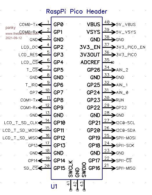 Depending on how much data you want to save (without using an SD card), you may be able to make use of variable save and restore using a longstring as a psuedo stack. Doug. ... almost all of the Maximites, the MicromMites, the MM Extremes, the ArmMites, the PicoMite and loving it! |
||||
| panky Guru Joined: 02/10/2012 Location: AustraliaPosts: 1094 |
Lew, Keep in mind that the Pico does not really have a low power mode so running from a battery for any length of time may not be the best solution - as Mick suggested, running from the car battery may be a better alternative of else use something like the STM32L43x series with an eink display. Doug. ... almost all of the Maximites, the MicromMites, the MM Extremes, the ArmMites, the PicoMite and loving it! |
||||
| lew247 Guru Joined: 23/12/2015 Location: United KingdomPosts: 1676 |
Thanks both, I realy don't want to use the cars power because that would mean hooking it up. I wanted something simple self contained that could sit on the dash in front of the driver, that I can take with me if I get a different car anytime. I'm going to use 2 X IFR26650 3.4Ah batteries in parallel, so I'll have 6.8Ah of battery power. The gps unit uses a maximum of 75mAh, when it's updating normally it's 25mAh and when in low power mode between 1 and 5mAh. So I reckon that will be plenty of power to power that will keep the unit alive when it's in low power mode and the display off. It will charge anytime the sun is out as it lives on the dash that will be at least 6 hours a day. The car doesn't get driven much since Corona, so its really only local trips with a longer drive once a month maybe. I'd like to set the gps module to low power mode once it's not moved for a set period of time using the commands but no idea how to send that via serial with MMbasic To wake the module I'm thinking some kind of movement sensor that wakes the pico once it detects an interupt and then it sends the wakeup signal to the gps and display. Might not work and I might be wasting my time but ... |
||||
| Mixtel90 Guru Joined: 05/10/2019 Location: United KingdomPosts: 5705 |
Although you *can* reduce the current consumption of the PicoMite, you don't gain much and there's no specific "wake up" input so it has to be running and either scanning an input or sitting in a loop waiting for an interrupt. If you watch the baud rate that you need for comms you might be able to set the CPU speed low to reduce current, but you can't speed it up under software control as speed changes cause a reset. I suppose you just send a string... PRINT#1 chr$(x)+chr$(y)+chr$(z) or peel values out of an array and send them in a loop Mick Zilog Inside! nascom.info for Nascom & Gemini Preliminary MMBasic docs & my PCB designs |
||||
| lew247 Guru Joined: 23/12/2015 Location: United KingdomPosts: 1676 |
Can anyone tell if I have a type A or type B display? clickable images to get larger size    |
||||
disco4now Guru Joined: 18/12/2014 Location: AustraliaPosts: 843 |
Hi Lewis, Not sure of the designations A and B but lets say type A is the one that exposes the LED Anode as LED pin and you need to supply 3.3V and possible current limiting resistor or a driver circuit if you want to drive via PWM. The Cathode of the LEDs are to ground via a 3.9ohm resistor. From my experience the size is also written as 240*320 (note the *). This is the one you have. The one below is Type B which can be driven at a logic level. (no reason it can't have 3.3v connected ). They will have a transistor Q1 and resistors R5 and R6 that are the driver circuit for the LED. The base of the transistor via a resistor is exposed as the LED pin. I have noticed that the size is also written 240X320 (notice the X).These seem to be the later ones. 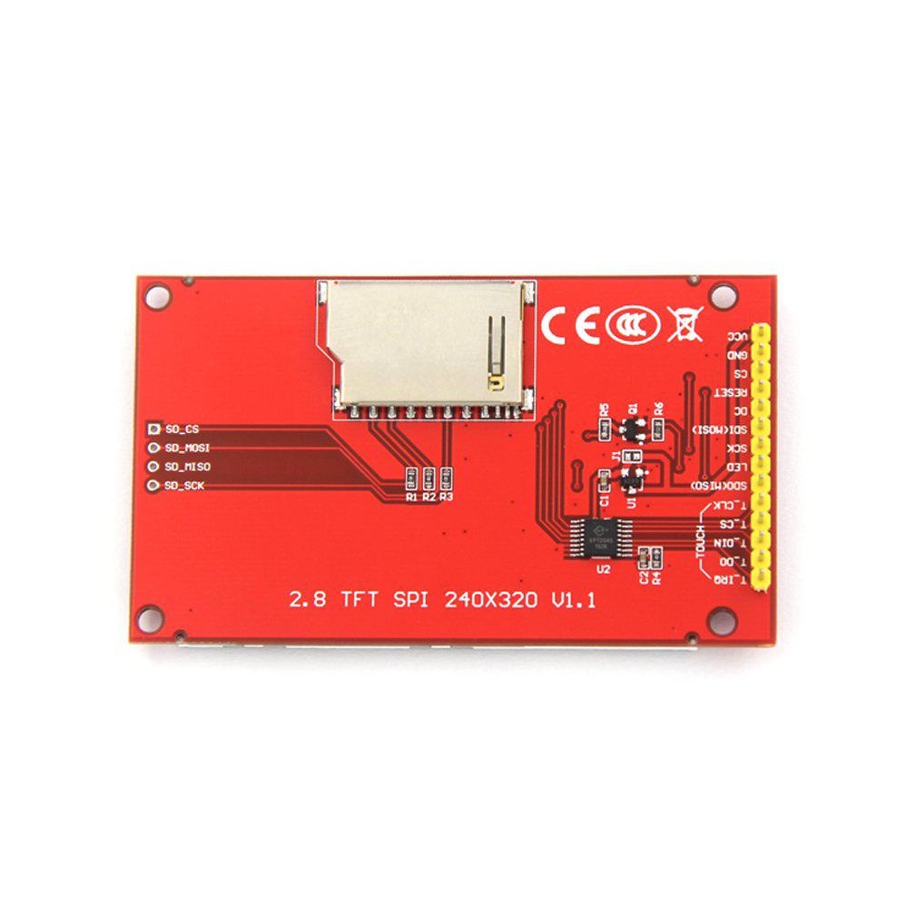 Latest F4 Latest H7 |
||||
| Mixtel90 Guru Joined: 05/10/2019 Location: United KingdomPosts: 5705 |
That's correct. Lewis has got the A and B terminology from my Backpack manual. It's definitely a type A according to that. Mick Zilog Inside! nascom.info for Nascom & Gemini Preliminary MMBasic docs & my PCB designs |
||||
