
|
|
Forum Index : Microcontroller and PC projects : PMM (Pico Mains Monitor)
| Page 1 of 2 |
|||||
| Author | Message | ||||
| Volhout Guru Joined: 05/03/2018 Location: NetherlandsPosts: 3496 |
This post does not really fit the forum. Origin of this forum is about generating electricity (in Australia) from wind and solar. I am living in Netherlands where electricity is provideed via national grid, and I am connected to it. In the transition to green however the grid get's burdened with many local electricity suppliers. In my neighborhood solar panels are popping up like fungus on blue cheese. And recently I have lost 2 mains adapters. Technician as I am I noticed by opening up the adapters that in both cases the input overvoltage protector (MOV) was blown. So I am worried the grid voltage exceeds normal voltage tolerances. To measure these, I am developing this mains voltage logger based on a RPi pico running MMBasic. For this to work you need at least 5.07.b17. Here are some pictures of the development. I am using a small bell transformer for isolation from the mains and a voltage divider using ADC in the pico on GP26. The logger measures continuous in the background and samples the mains at 2kHz (40 samples per sine wave at 50Hz) using the ADC command. Using of MATH functions process the data to an RMS value (actually MATH(SD array()) does a perfect ac-rms on it's own including dc cancelation. It is work in progress as you can see from the pictures. Missing is: - RTC - FFT graph - Waveform Graph - logging events on SD card I plan to power the setup from a powerbank with charger connected in first instance. So if mains drops, it is still registered. 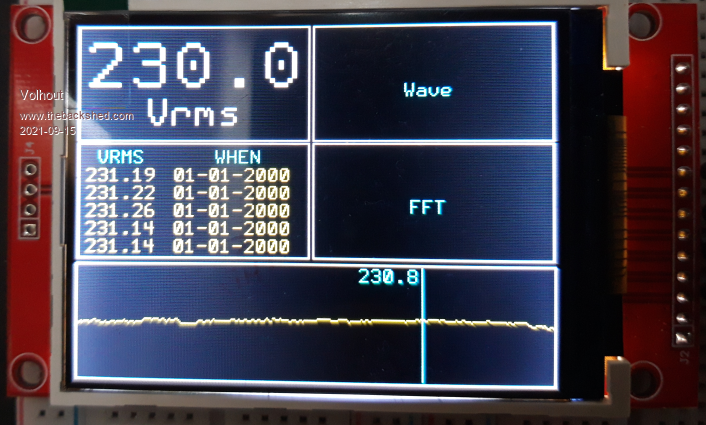 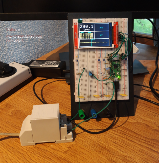 Edited 2021-09-15 18:46 by Volhout PicomiteVGA PETSCII ROBOTS |
||||
Chopperp Guru Joined: 03/01/2018 Location: AustraliaPosts: 1032 |
I know at my place in sunny QLD AU, we get over 260VAC at times when the sun is shining & the loads are light. The inverters are supposed to be limited to about this voltage but ours is not. The installer was not interested in resetting it. The only real casualty I've had was with a fairly large SMPS I got on line awhile ago. One of the series mains filter capacitors let out heaps of smoke & unpleasant odours. Got full refund though. The voltage ratings of most stuff advertised doesn't really fit the maximums we get here. Brian ChopperP |
||||
| Mixtel90 Guru Joined: 05/10/2019 Location: United KingdomPosts: 5705 |
I'd suggest a fusible resistor followed by a MOV on the secondary of the transformer in addition to anything else. Just in case. Mick Zilog Inside! nascom.info for Nascom & Gemini Preliminary MMBasic docs & my PCB designs |
||||
| CaptainBoing Guru Joined: 07/09/2016 Location: United KingdomPosts: 1985 |
this is quite a problem in UK. Because "no voltage drop no current flow" people with panels on a feed-in tariff have to be generating at a higher voltage to push back into the grid so they do anything other than cover drop-outs in high demand periods (they naturally want to be earning as much as possible). So person A notices their payments have dropped because their energy feed-in has dropped, so they call the "solar man" he comes round and tweaks their kit up a volt or two. Now person B has the same problem and so-on throughout the community. I have seen mains voltage at almost 260V (UK nominal is 240) in some areas because of this and it isn't going to get better any time soon. Of course this endless tweaking shouldn't happen but how do you explain the complex problem to people that know only that they want to earn the amazing amounts the sales guy promised and nothing about kirchoff, ohm et al . Edited 2021-09-15 22:03 by CaptainBoing |
||||
| Mixtel90 Guru Joined: 05/10/2019 Location: United KingdomPosts: 5705 |
From what I understand (we used to install PV systems in the UK) the domestic side isn't a big problem. That's because in most cases the arrays are relatively small compared to the load. There will be excess generation sometimes, but it's not enormous. The PV inverter usually tracks the grid voltage to only allow a certain amount of feed-in, no matter what the conditions are. Many will keep it low or non-existent until the locally connected load is satisfied because if you don't do that you are paying for electricity at a higher rate than you can get paid for generating it. Industrial consumers, with large arrays, have to have export restriction in place, otherwise their DNO will be round to disconnect them! That's because they are capable of affecting distribution wiring and protection equipment on the network through over-generation. There is a set of specific equipment that has to be installed on those sites or they won't get connected. Severe over-volt problems in the UK are usually caused by local problems, such as a large factory shutting off some big loads or complaints about low voltage off one sub (maybe because of a new housing estate) turning into complaints about high voltage on another. Both those usually get fixed eventually, but it might be when new subs get installed or older ones updated or readjusted. It's worth telling your DNO if there are frequent over-voltage issues. I know of an area not far from here who do have a problem, but they are right on the sub feeding a huge factory complex. Short of moving the domestic stuff onto a different HV line it's not likely that their problem will get fixed. Edited 2021-09-15 22:42 by Mixtel90 Mick Zilog Inside! nascom.info for Nascom & Gemini Preliminary MMBasic docs & my PCB designs |
||||
TassyJim Guru Joined: 07/08/2011 Location: AustraliaPosts: 5883 |
In Australia, the inverters are supposed to cut out with a voltage over 254V. Australia used to have a nominal voltage of 240V but was reduced to 230V some time ago. I don't think the supply companies have bothered to change the taps on too many transformers so we run close to the maximum at times. I am glad I am no longer responsible for any of that. A few years ago I built a disturbance recorder based on a MX170 to record the AC waveform for a number of cycles before and after a sudden change in voltage. I must get back to it. Another half done project to finish. Jim VK7JH MMedit MMBasic Help |
||||
| Mixtel90 Guru Joined: 05/10/2019 Location: United KingdomPosts: 5705 |
The paperwork was changed to "harmonise" the 240V UK mains with the 220V European mains without actually changing anything. :) Mick Zilog Inside! nascom.info for Nascom & Gemini Preliminary MMBasic docs & my PCB designs |
||||
| phil99 Guru Joined: 11/02/2018 Location: AustraliaPosts: 1773 |
@Mixtel90 Same in Aus. When the nominal voltage changed from 240 to 230 the percentage over and under voltage limits were also changed resulting in exactly the same actual limits. The distribution companies were free to do nothing, and they did nothing. The problem of miss-match between solar / wind output and demand is slowly being addressed by adding large battery banks to the grid. |
||||
| Volhout Guru Joined: 05/03/2018 Location: NetherlandsPosts: 3496 |
When United Kingdom joined Europe (yes they did once) there was an agreement to harmonize mains voltages. They settled on 230V (mid between 220 and 240) for the whole of Europe. The bulk of the countries on mainland Europe where using 220V at that time. Since this change would affect the whole grid (pan European) the whole of Europe changed to 230V. And then Britain itself decided to stay 240V..... The Brits have a history of being stubborn. That may be why they where able to resist Hitler until the Yanks came. So be proud to be British, be realize what you do to the rest of the world. Volhout. PicomiteVGA PETSCII ROBOTS |
||||
| CaptainBoing Guru Joined: 07/09/2016 Location: United KingdomPosts: 1985 |
no we don't   Edited 2021-09-16 20:45 by CaptainBoing |
||||
| Mixtel90 Guru Joined: 05/10/2019 Location: United KingdomPosts: 5705 |
The UK standard, pre-harmonization, was (by law) 240V i.e. 225.6 to 254.4 V. The EU wanted harmonization across Europe with a 220V system, but that would have cost the UK millions to implement so an agreement was made to change UK law to allow 230V i.e. 216.2V to 253V. That allowed EU harmonization yet kept the 240V equipment that would have had to be replaced otherwise. It was the only way really, changing everything from 240V to 220V for the sake of EU paperwork would have been madness. Our "nominal voltage" is now 230V, but the actual voltage in most areas is 240V or just above. Mick Zilog Inside! nascom.info for Nascom & Gemini Preliminary MMBasic docs & my PCB designs |
||||
| MikeO Senior Member Joined: 11/09/2011 Location: AustraliaPosts: 275 |
Moons ago when I was working and a Field engineer, much of the instruments I worked on were in Hospital or university labs. Most contained HV supplies for Photo Multiplier Tubes, which had a habit of failing overnight or the weekend as the mains supplies went up when the day time loads came off, If suspected we would perhaps put a logger on the supply and 254-258vac would not be unusual killing supplies or dynode strings. If it wasn't that maybe the odd clean of fried Mice  Codenquilts |
||||
| Volhout Guru Joined: 05/03/2018 Location: NetherlandsPosts: 3496 |
Finally got time to pick this up again. The code is growing quite big for the build in editor. I have been using a lot of defines based on MM.Hres and MM.Vres, but it is becoming so complex I may drop the variables and hard-code (just to clean up the code). It is going to be 1 one-off anyway. Tried to upload a "BMP" file, created by SAVE IMAGE xxx, but the forum would not cooperate... PicomiteVGA PETSCII ROBOTS |
||||
| phil99 Guru Joined: 11/02/2018 Location: AustraliaPosts: 1773 |
Converting BMP to PNG or JPG first seems to allow upload. |
||||
| Tinine Guru Joined: 30/03/2016 Location: United KingdomPosts: 1646 |
@CaptainBoing   |
||||
| Volhout Guru Joined: 05/03/2018 Location: NetherlandsPosts: 3496 |
jpg 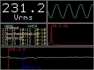 png 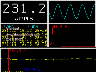 png looks better, even at 100% quality of jpg Pico, LCD and 6 components.... And a lot of math... thanks Peter, especially for the ADC function. The code runs 3 levels interrupts top level: sampling (machine code, Peter does all that) lower level: interrupt buffer full lowest level: timer interrupt (refresh screen every second) What I still have to do: - implement RTC (I now enter date and time, but the pico time$ is not really accurate, need to add a DS3231). - save events to SD card (complete ADC samples array, so you can actually analyze what went wrong, a single peak, or constant level, or outage). Once I have a publish-able version (with comments) I will publish here. Volhout Edited 2021-10-23 18:08 by Volhout PicomiteVGA PETSCII ROBOTS |
||||
| Volhout Guru Joined: 05/03/2018 Location: NetherlandsPosts: 3496 |
Small update The project is not done yet, I still have to implement the SD card storage of events and logs. But some changes where needed 1/ Calculating the mains frequency from the FFT gave jittery results and some drift. Therefore the mains frequency is no measured using the picomite frequency measurement and some averaging. 2/ The mains isolation was in a transformer. But the (small) transformer gave additional distortion. (original plan wat to use the transformer to both power the pico and LCD, and use a isolated measurement input. I now use a solid state (opamp) circuit with (dual) 10 Meg ohm high voltage resistors. This is far superior in distortion. Powering the pico will use a phone charger. 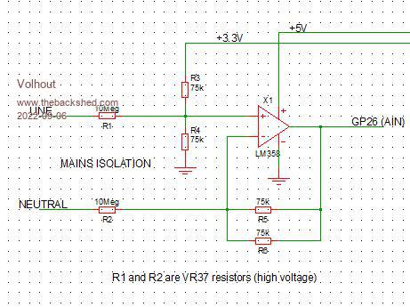 3/ some cosmetic changes (minor) 4/ the trend graph shows 320 minutes (5 hours) of rms voltages. Attached graph below shows the influence of the sun setting on the mains voltage (solar panels in the neighbourhood). 5/ RTC implemented 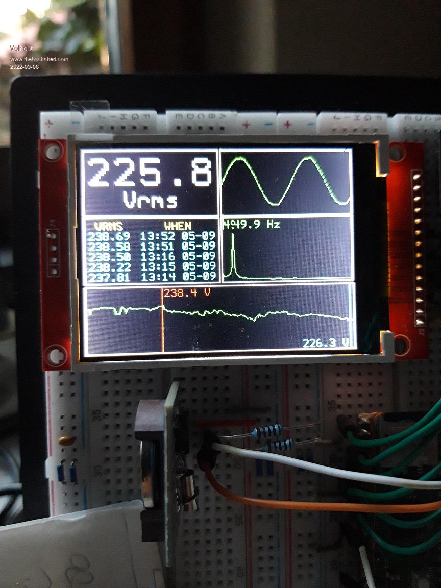 Edited 2022-09-06 18:58 by Volhout PicomiteVGA PETSCII ROBOTS |
||||
| Mixtel90 Guru Joined: 05/10/2019 Location: United KingdomPosts: 5705 |
This is a really nice project. Useful too. :) Mick Zilog Inside! nascom.info for Nascom & Gemini Preliminary MMBasic docs & my PCB designs |
||||
| Octatron Newbie Joined: 01/04/2015 Location: United KingdomPosts: 22 |
Good project. Strangely enough yesterday I started a similar project to measure power consumption of our house. Searched the Back Shed as best as I could and came across this article Measuring RMS Using MMBASIC link http://www.fruitoftheshed.com/MMBasic.Measuring-RMS-algorythm-using-MMBasic.ashx?HL=rms There is code with this article which I have started to try and get working on a Micromite+, not got far yet though. I have a current transformer which gives 1V ac for 30A, so measure this and the supply voltage and the power can be worked out. Hope this helps. |
||||
| Volhout Guru Joined: 05/03/2018 Location: NetherlandsPosts: 3496 |
Hi Octatron, Please post your project on this forum once you feel to it. We are eager to learn what you have achieved. The micromite will perform the RMS conversion nicely in basic. The sampling frequency is limited by the speed of the basic interpreter. In the example you refer to the ADC is sampled at maximum speed the basic interpreter can do, around 4kHz. The newer Picomite has additional commands that simplifies RMS measurements. - sampling the ADC in the background to an array - calculating RMS with a single MATH command The picomite ADC however is not as good as the one in the MX170. Edited 2022-09-07 20:12 by Volhout PicomiteVGA PETSCII ROBOTS |
||||
| Page 1 of 2 |
|||||
