
|
|
Forum Index : Microcontroller and PC projects : Thinking about a new Pico PCB design for integrating into a keyboard
| Page 1 of 5 |
|||||
| Author | Message | ||||
| matherp Guru Joined: 11/12/2012 Location: United KingdomPosts: 8578 |
There seems to be some interest in building the PicoMite (VGA) into a keyboard so I was thinking about a suitable design. Seems to me it needs to be a long thin strip design with all the connectors along one side Power socket Pico VGA port 40-pin header SDcard socket Reset switch There would be an internal header to connect the PS2 lines from the keyboard so the cable would be removed rather than a PS2 socket The board should have a header for a RTC but I suspect that would be about it. Does it need a separate power connector or just the micro-USB on the Pico? Thoughts? |
||||
| Mixtel90 Guru Joined: 05/10/2019 Location: United KingdomPosts: 5722 |
I was wondering about this too and came to the conclusion that the pcb probably had to be as flat as possible - unless someone knows of a suitable source of deeper keyboards at less than eye-watering prices. Based on that I considered surface-mounting the Pico and using a USB-A for power and/or console connection. They are more rugged than microUSB and far easier to solder than USB-C. This arrangement also allows the Pico to be mounted along the length of the pcb, keeping the depth to a minimum. The VGA connection may be awkward to do, but another USB-A could be used for the keyboard. Mick Zilog Inside! nascom.info for Nascom & Gemini Preliminary MMBasic docs & my PCB designs |
||||
| Amnesie Guru Joined: 30/06/2020 Location: GermanyPosts: 379 |
Building it into an existing keyboard? I really don't know how this sould be solved properly; there are too many keyboard models. Even in my beloved mechanical Cherry keyboards isn't enough space. Well... enough space, but "wasted" here and there... The best way would be to build a whole PS/2 keyboard with the picoVGA on the pcb but - of course - this costs money. There are a lof of open source / open hardware keyboard projects but all of them will cost some money due to the fact that they make it right, meaning: mechanical keyswitches, not rubber dome bullsh*t. The overall design isn't a problem, only the money is. In the end I guess it will be a dream, but i love the idea! Edited 2022-04-15 02:21 by Amnesie |
||||
| Amnesie Guru Joined: 30/06/2020 Location: GermanyPosts: 379 |
I have an idea to save much space! I have got a small chineese monitor where the VGA socket is a small mini USB b socket (5 pin). See: "https://upload.wikimedia.org/wikipedia/commons/thumb/8/82/USB_2.0_and_3.0_connectors.svg/1280px-USB_2.0_and_3.0_connectors.svg.png" This can be a real solution for the tight space. I think a regular D'Sub 15 is definitly not an good idea. I would not suggest inplementing the 40pin connector, for what reason should anyone route the pins for the VGA to the connector? If we would only route the pins which are not used to the connector we could save space and shrink it to a 15 pin connector. Edited 2022-04-15 02:52 by Amnesie |
||||
| Mixtel90 Guru Joined: 05/10/2019 Location: United KingdomPosts: 5722 |
The problem with the mini connectors is soldering them - it takes a steady hand and magnification. The alternative is to use breakout boards, but supply can sometimes be a problem with those. Mick Zilog Inside! nascom.info for Nascom & Gemini Preliminary MMBasic docs & my PCB designs |
||||
| Amnesie Guru Joined: 30/06/2020 Location: GermanyPosts: 379 |
Normally I would agree but the Mini USB type B (thorugh hole) is no problem at all - and I really hate little smd-like parts. I think we will not get around this to make things small... I am working on it with this connector and a smaller 15 pin connector plus the things peter mentioned just for fun to see how small we can get, I'll update everyone here. Even if it is not the prefered way everyone get's an idea how small we can get. |
||||
| Mixtel90 Guru Joined: 05/10/2019 Location: United KingdomPosts: 5722 |
"How small we can get" might involve not using a Pico but one of the smaller RP2040 modules. :) VGA will be interesting as it will be either a special lead (has to be short unless there are screened cores) or an external adapter unless we can find enough height for a DB15. Mick Zilog Inside! nascom.info for Nascom & Gemini Preliminary MMBasic docs & my PCB designs |
||||
| al18 Senior Member Joined: 06/07/2019 Location: United StatesPosts: 174 |
I think youÆll find it difficult stuffing a Pico, 40 pin header, VGA connector inside a USB case. The Raspberry Pi foundation had to redesign the Pi 4 into the the Pi400. I like the design of the Pi400. I would like to see a PicoMite designed to fit a stackable acrylic Raspberry Pi case. These cases just have top and bottom acrylic held together with 4 brass standoffs. There is a screw pattern to fit the 4 screws for the Raspberry. YouÆll find this case, that holds up to 4 PiÆs on Aliexpress for $5 to $11. This plus is there are NO sides to these cases, so they can accommodate connectors on any or all sides of the board. This is also a positive for Raspberry PiÆs because the same case accommodates every Raspberry Pi model ever produced. Edited 2022-04-15 03:22 by al18 |
||||
| Amnesie Guru Joined: 30/06/2020 Location: GermanyPosts: 379 |
Since there a so many DSub 15 connectors and adaptors for self assembly / soldering (sorry I don't know the right word in english) I see no problem to modifi a normal USB cable with it's screen to ground housing all the "vga data" inside. That's the way my little chineese monitor works. Why shouldn't work it for the pico? |
||||
| Mixtel90 Guru Joined: 05/10/2019 Location: United KingdomPosts: 5722 |
You don't want a lead that allows you to plug the VGA socket of a monitor into the USB socket of anything else. It's not safe. Something *will* break at some point. There is a mini VGA "non-standard" connector. https://en.wikipedia.org/wiki/Mini-VGA Alternatively, a polarized connector of 6 pins or more would probably do. Mick Zilog Inside! nascom.info for Nascom & Gemini Preliminary MMBasic docs & my PCB designs |
||||
| Amnesie Guru Joined: 30/06/2020 Location: GermanyPosts: 379 |
Maybe you are right about the "human factor" of error. For the moment I leave it in the layout as a "placeholder" for something with a similar footprint. I am aware of the inoffical mini VGA, but I don't checked the availablility. I make some progress and share the PCB layout in an hour or so... Just to share some thoughts and show the overall dimensions with through hole components. |
||||
| Mixtel90 Guru Joined: 05/10/2019 Location: United KingdomPosts: 5722 |
I've been trying to find mini VGA connectors but they don't seem to be available, although you can get adapters to fit them. Mick Zilog Inside! nascom.info for Nascom & Gemini Preliminary MMBasic docs & my PCB designs |
||||
| Amnesie Guru Joined: 30/06/2020 Location: GermanyPosts: 379 |
This is how far I got: 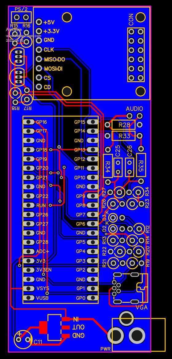 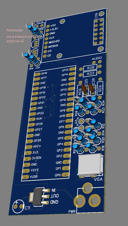 DIMENSIONS 39mm * 95mm Really really tight but I think with this dimensions it is possible, at least to some degree. As we can see we must do some compromise with connectors. Otherwise we must switch to SMD technique instead of through hole components... But this would be a bad soloution so solder. You can see that there is still more trace routing to come. I quickly explain the sections: Upper left is the logic shifter for keyboard, right to it is the adafruit micro sd breakout on spacer to fit underneath the 2x6 connector for GPIO. On the right to the PICO is the VGA resistor network as well as on the top the passive audio filter network. And as said, for the moment it is just an idea to show and test some component placement or even the possibility to fit everything. VGA connector can be a different type but MUST be a similar footprint. I am doing a short break now :) Greetings Daniel Edited 2022-04-15 05:56 by Amnesie |
||||
| Amnesie Guru Joined: 30/06/2020 Location: GermanyPosts: 379 |
Making some progress, I think this is really possible! But as I said; if it should fit in a keyboard it we can not go much bigger, so my suggestion is to fit a VGA connector seperatly or find a good substitute connector which is available (!) on the market. 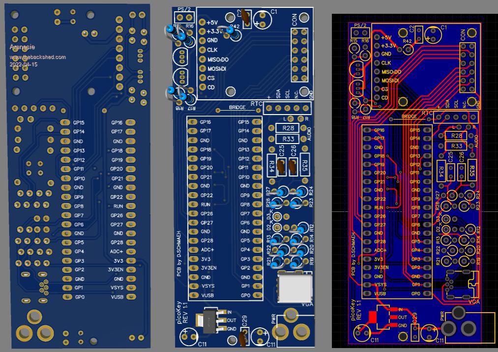 So far it is on the board: - RTC (mini version for the RaspberryPi) - Adafruit Sd breakout on spacer - PS/2 Keyboard out as Peter suggested via bare pins / connection Ā-> Level Shift transistors are correct polarity, I used different type (2N7000) - Audio via pin connector - VGA (in search of soloution) - LDO 3V3 (AMS1117, 800mA) TODO: - forgot the 3V3EN COMPROMISES: - PICO micro USB not accessible (solution would be to turn the PICO 90 degrees, but this is a no-go, since it would make the overall dimensions not accepptable) - instead of 40 pin connector I took a 12 pin connector and routed following pins to it: GP0,GP1,GP2,GP3,GP4,GP5,GP27,GP26,GP22,GND,3V3(on the picture it is GP28, changed that, since 3V3 is more important) There is and always will be some compromise... Any suggestions so far? :) Edited 2022-04-15 09:33 by Amnesie |
||||
bigmik Guru Joined: 20/06/2011 Location: AustraliaPosts: 2870 |
Hi Peter, All, It is very funny that I was æthinkingÆ about this concept just last week. I just built up a Silicon Chip pico board and thought about building a all in one keyboard design but then I tossed it into the burner as there are so many different keyboards that it would be impossible to create a one design fits all design. I also thought about a æfalse bottomÆ added to the underside of the keyboard and this could have some merit and be pretty thin and not add too much to the height of the keyboard. Then pondering further I decided that a better solution would be to build the pico into a vga monitor, this could be mounted internally to the monitor or added to the rear panel, this design could be accommodated by just about every monitor available and in the end only one cable between the monitor and keyboard. To build into the keyboard would mean two cables, one for the monitor and the other for power input. I am finding this thread very interesting and am listening to other peoples input in this. The Pico is a very cheap, and best of all is readily available and is a logical path for cheap controllers. Keep up the great work Peter, Regards, Mick Edited 2022-04-15 10:52 by bigmik Mick's uMite Stuff can be found >>> HERE (Kindly hosted by Dontronics) <<< |
||||
| bigmik Guru Joined: 20/06/2011 Location: AustraliaPosts: 2870 |
Hi All, Re. VGA connectors, An easier/more workable approach without going to non standard connectors would be to use a solder tail vga connector and run the wires to the pcb as required. There are only 6 wires to solder so should be easy enough and this allows the VGA to be mounted wherever is convenient to suit your kb. The solder tail connector is much smaller than any pcb mount one. Regards, Mick Mick's uMite Stuff can be found >>> HERE (Kindly hosted by Dontronics) <<< |
||||
| Rickard5 Guru Joined: 31/03/2022 Location: United StatesPosts: 328 |
WoW this is the Neatest Idea I Love it I turned the volume on the monitor to max and could hear sound. Thanks Stanleyella |
||||
| al18 Senior Member Joined: 06/07/2019 Location: United StatesPosts: 174 |
A PicoMite board the size of a VESA mount sounds like a great idea! Has the advantage of keeping my desk clear - I have very little space on my desk. |
||||
| Amnesie Guru Joined: 30/06/2020 Location: GermanyPosts: 379 |
I think a ĀVESA mount is a different approach, you can not access the GPIO (unless you are willing to accept long wires) etc... The downside of building it into the monitor is, that it isn't as portable as a keyboard. Of course; everything has it's right to life. I think I will end up with different versions. One will be a "as minimal as possible" to maybe fit the inner of a keyboard. The other will support a full VGA DSUB 15. I am working on this right now and moving some components to keep it at a maximum length of 10cm (EDIT: check! It fits) Even if this won't work out to fit a keyboard we have another two versions of a small footprint picoVGA :) Edited 2022-04-15 15:23 by Amnesie |
||||
| bigmik Guru Joined: 20/06/2011 Location: AustraliaPosts: 2870 |
Hi Amnesie, If you need more length than 10cm, design a pair of boards that mate via R/A male & Female header pins and you can join 2 PCBs to make a 20cm long one. Regards, Mick Mick's uMite Stuff can be found >>> HERE (Kindly hosted by Dontronics) <<< |
||||
| Page 1 of 5 |
|||||
