
|
|
Forum Index : Microcontroller and PC projects : picoMite Mini
| Page 1 of 2 |
|||||
| Author | Message | ||||
| Amnesie Guru Joined: 30/06/2020 Location: GermanyPosts: 372 |
Hello everyone, I am opening a new thread for this, because I decided to release a simple and plain "mini" version of the picoVGA, which you can expand with an expansion board by utilizing the female / male headers on the board to connect them properly. The expansion board offers a bigger Real Time Clock, not the mini version, which is more common and you can change the battery. Also the GPIO is lead to the external this way and a barrel jack can deliver all the juice :) I decided to give you two versions of the picoVGA mini, one has got a PS/2 connector, the other has a normal USB connector. Why? Because I have only one single keyboard with a PS/2 connector, all other keyboards are equipped with USB-connectors which support the PS/2 protocoll, too. This way you don't need an adaptor and you don't need too big standoffs / spacers for the adafruit micro SD breakout. Speaking of that, it uses the blue one, that is "5V ready". I have really great experience with the superior quality of adafruit and not the cheap ones (gold contacts etc.) Important to know is that the silk screen orientation of the level shift transistors on my version appears to be turned 180 degree, this is because I am using the more (at least where I live) common 2N7000 transistors. So this is not a fault, keep in mind that you can use other transistors. The board is double checked and I am ordering some tomorrow at JLCPCB. I am publishing here my Gerbers and "raw" EasyEDA design files, so you can do what you want with it. Use it as inspiration for own designs :) The original intention was to create an "as small as possible" board to fit in a keyboard, but more and more I realized, that it is not possible without pure SMD technique (at least to make really sense). A pure SMD version will come at a later point in time. PS/2 Version: 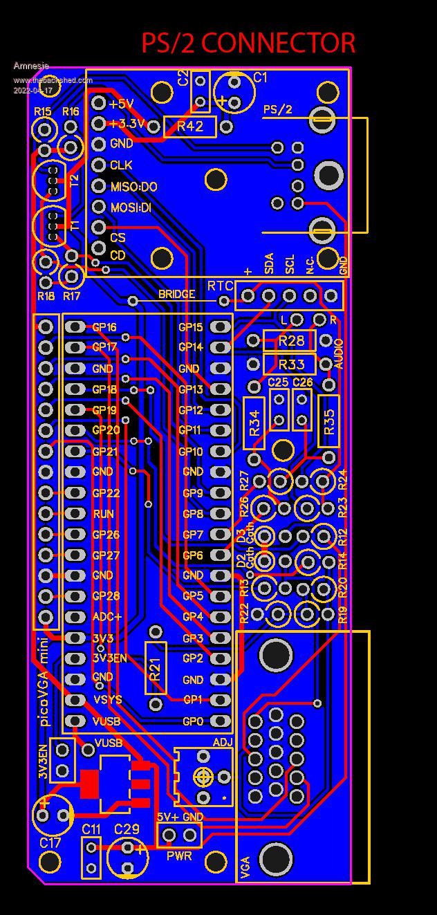 USB Version: 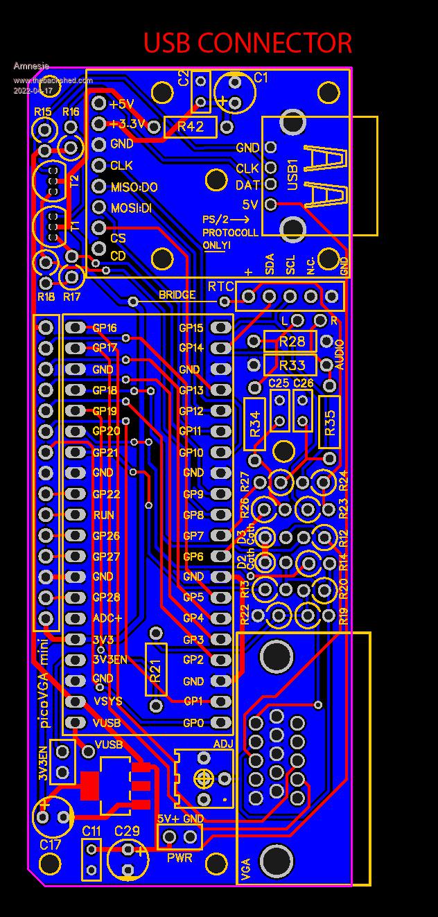 Expansion board: 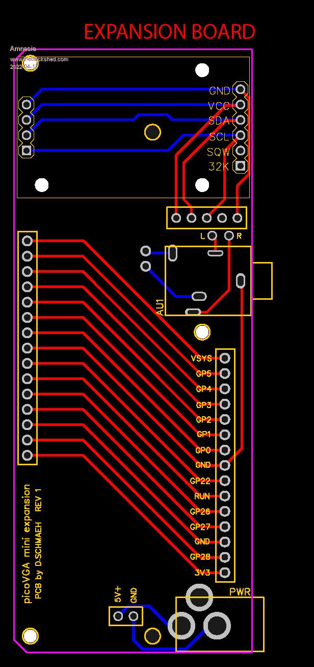 Gerbers & "raw": Gerbers.zip Have fun with it! Greetings Daniel |
||||
| panky Guru Joined: 02/10/2012 Location: AustraliaPosts: 1094 |
Nice work Daniel. Thanks, Doug. ... almost all of the Maximites, the MicromMites, the MM Extremes, the ArmMites, the PicoMite and loving it! |
||||
| TheRockGod Newbie Joined: 01/04/2022 Location: AustraliaPosts: 8 |
Fantastic...Just what I was looking for! �Only 1 problem, it appears as though the gerber file for the USB version, is actually the PS2 version. �In my excitement at seeing this design, I uploaded the "USB" to JLPCB, only to realise when it was too late, that it was in fact the PS2 connector version. �I also checked the PS2, version - same (PS2 connector). �Can you pls repost with the USB connector version, so I can do another order (I hate those ps2/usb adapters). �:-) Many thanks, and great work!  Tony Edited 2022-04-18 17:52 by TheRockGod |
||||
| Amnesie Guru Joined: 30/06/2020 Location: GermanyPosts: 372 |
Ah, sorry! I don't know how this could happen, here are the correct USB Gerbers! Gerber_mini picoVGA_usb.zip Greetings Daniel |
||||
| al18 Senior Member Joined: 06/07/2019 Location: United StatesPosts: 174 |
FYI you can view gerber files for free using a program such as Pentalogix Viewmate. I�m sure there are other free gerber viewer programs out there, but I like Viewmate because it is virtually unchanged for the past 20 years. You�ll need to supply your email address to download the program, but it�s pretty painless and they don�t sell your email address. |
||||
| TheRockGod Newbie Joined: 01/04/2022 Location: AustraliaPosts: 8 |
Thanks Daniel, I've ordered these now :-) |
||||
| Amnesie Guru Joined: 30/06/2020 Location: GermanyPosts: 372 |
My PCBs are still in procution, maybe you are faster than me in getting them fired up and running :) |
||||
| LechU Newbie Joined: 18/01/2022 Location: PolandPosts: 3 |
Could You PLEASE add "PCB_mini picoVGA_usb_2022-04-16.json" file? THX, Leszek |
||||
| Mixtel90 Guru Joined: 05/10/2019 Location: United KingdomPosts: 5705 |
Hi Leszek, and welcome to TBS. :) I'm surprised that you would need a json file to get PCBs made. The set of Gerber files wouldn't normally include one, just a file for each layer used and a drill file. Edited 2022-04-22 04:49 by Mixtel90 Mick Zilog Inside! nascom.info for Nascom & Gemini Preliminary MMBasic docs & my PCB designs |
||||
| Amnesie Guru Joined: 30/06/2020 Location: GermanyPosts: 372 |
Hey Mick, the *.json-file is the file-format that EasyEDA uses for it's own PCB layouts. With this file you can edit my "raw" layout and modify it the way you like. Since the whole community lives from open hardware / open software, everyone is free to use my PCB layouts for whatever purpose and modify it. I think this is what he is asking for. Here is the file: PCB_mini picoVGA_usb_2022-04-22.zip Edited 2022-04-22 08:09 by Amnesie |
||||
| LechU Newbie Joined: 18/01/2022 Location: PolandPosts: 3 |
Thank You �  I'm new in electronics and I want to learn how to project PCB's. I think that explore/study/modyfy someones project (especially when this projects made by experts �are well made  can help me can help me  ) - Thanks again. ) - Thanks again.Leszek Edited 2022-04-22 15:10 by LechU |
||||
| Amnesie Guru Joined: 30/06/2020 Location: GermanyPosts: 372 |
It's all done and tested; here are some pictures and new Gerbers for exactly this version: 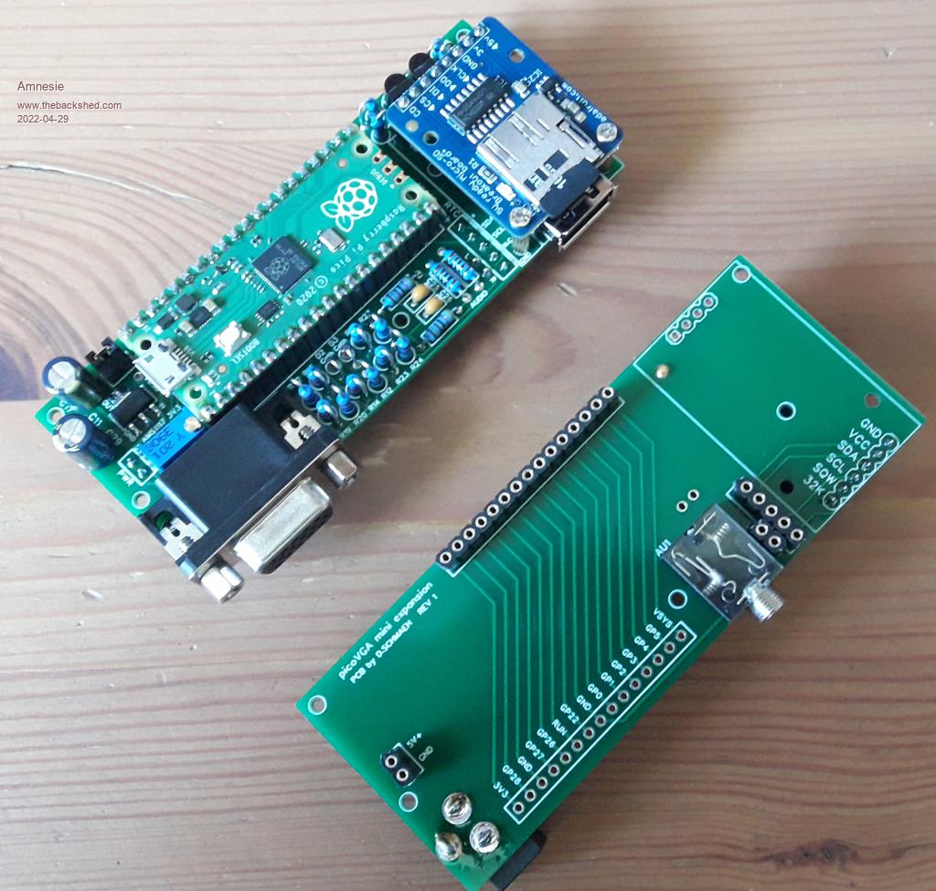 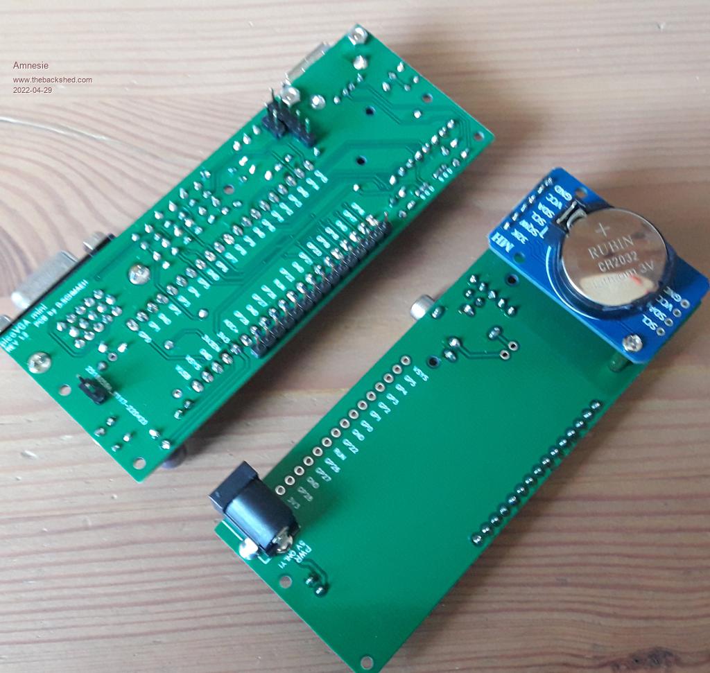 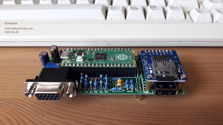 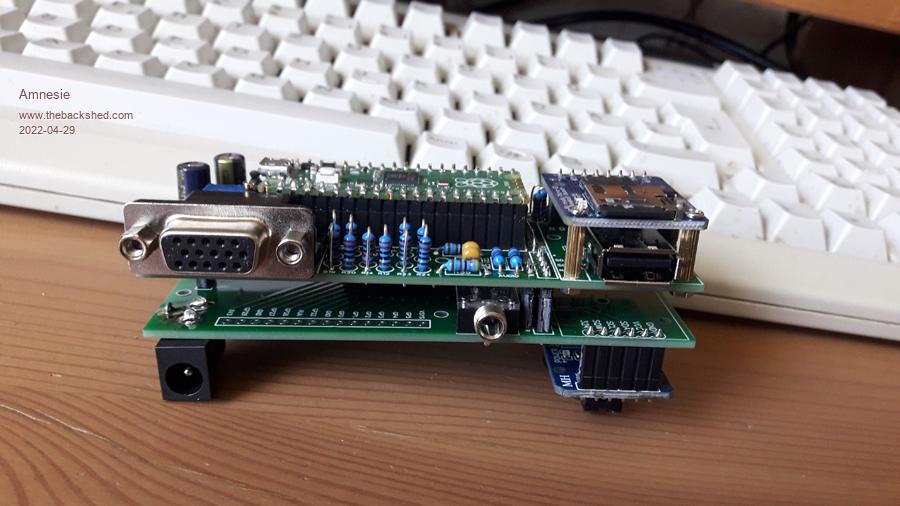 Gerber_mini picoVGA_expansion_2022-04-28.zip Gerber_mini picoVGA_usb.zip |
||||
| lizby Guru Joined: 17/05/2016 Location: United StatesPosts: 3008 |
Nice work. Congratulations. PicoMite, Armmite F4, SensorKits, MMBasic Hardware, Games, etc. on fruitoftheshed |
||||
| TheRockGod Newbie Joined: 01/04/2022 Location: AustraliaPosts: 8 |
That is a work of art!!! My boards haven't arrived yet, but tracking indicates they are close (in Australia)...hopefully, within a few days :-) |
||||
| Rickard5 Guru Joined: 31/03/2022 Location: United StatesPosts: 328 |
GOD I love that, Looks like an IBM Model M Keyboard is going to be sacrificed. as soon as I can get those off to get boards made I'm building a few :) I turned the volume on the monitor to max and could hear sound. Thanks Stanleyella |
||||
| Volhout Guru Joined: 05/03/2018 Location: NetherlandsPosts: 3490 |
Realty love to see this mounted inside a keyboard. Stacked together thee are pretty high. PicomiteVGA PETSCII ROBOTS |
||||
| TheRockGod Newbie Joined: 01/04/2022 Location: AustraliaPosts: 8 |
Got my boards today! Just putting one together now!!...I was wondering which transistors you used? I got the 2n7000, is the pinout the same as the silk screening??? Thanks |
||||
| TheRockGod Newbie Joined: 01/04/2022 Location: AustraliaPosts: 8 |
For 2n7000 transistors, DON'T follow the silk screening...put transistors in, opposite direction, to the silk screening. :-) |
||||
| Mixtel90 Guru Joined: 05/10/2019 Location: United KingdomPosts: 5705 |
According to the first post in this thread the silk screen is correct for 2N7000. Source should go to the 3V3 side and drain to the PS/2 side, which looks right to me. Facing the flat side of a 2N7000 the leads are 1-2-3, Source-Gate-Drain. Mick Zilog Inside! nascom.info for Nascom & Gemini Preliminary MMBasic docs & my PCB designs |
||||
| Amnesie Guru Joined: 30/06/2020 Location: GermanyPosts: 372 |
If you use my boards the silk screen is correct! I use the 2N7000 because they are more common than what the original PCB uses. |
||||
| Page 1 of 2 |
|||||
