
|
|
Forum Index : Microcontroller and PC projects : PicoMite PLC project
| Page 1 of 5 |
|||||
| Author | Message | ||||
| Mixtel90 Guru Joined: 05/10/2019 Location: United KingdomPosts: 5711 |
PicoMite PLC.zip This is something else that started as a wild idea while doodling. It's a sort of design-in-progress that may or may not be attempted sometime. :) I do these things mostly because they seem interesting. Every one is a learning exercise. lol This is a logic controller system based entirely on standard PicoMites. A base bord holds a master controller and a number of I/O card slots (I refer to a 6-slot board as having a master + 6 I/O slots). The slots are on a SPI bus, with a CS line each. I've kept it to 9 I/O slots to give a 10-position baseboard. The base shown in the zip file is 100mm x 150mm with 6 slots, but you can get a 3-slot board in 100mm x 100mm. Using addressable slots in this way uses a lot of pins on the master but gives fast access speed and means that there are no I/O board address switches to bother about. The SPI bus should easily be able to exceed 1MHz, with 10MHz not being unusual - I think that's quite feasible. SPI is handled very neatly in MMBasic so I think it's a good choice. The master board also carries a buck converter (TBD) to convert the 24V board supply to 5V to feed the I/O modules from the bus. There isn't a lot of current required from 5V, and it means that you can't attempt to run the system without the master card. It has two LEDs, Fault and Run which are fed out to the base, where Fault drives a mosfet with the drain available to connect a beacon or something. The Run signal operates a small relay with a changeover contact giving Run and Off status. COM1 is fed to a connector that could be used for external monitoring or whatever. The master can also monitor the 24V supply to ensure it is within spec for modules sourcing 24V to external loads. Each I/O board is 100mm x 50mm high and carries pluggable I/O terminals along the top. So, you can get a fully loaded 6-slot PLC into 150mm x 100mm x 50mm. The number of I/O per board depends on complexity. At the moment I have: 5-way : Opto-isolated input, Monitored IS switch input 8-way : High-side 800mA digital out 10-way : Non-isolated low side digital out, Non-isolated digital in A 6-slot base could, if you stick with just the 10-way boards, have 60 digital I/O. This is hardly earth shattering for the PLC world, but anything more would have needed bigger PCBs. The advantage of 100x50 is that you can get 2 out of a 100x100 "bargain price" pcb. :) Note that nothing plugs in apart from the I/O boards into the base and the I/O terminals. This is for reliability. Also, there are no special chips used other than the Pico boards. This is important at the moment as delivery times for even simple relay drivers is silly if you want them from reputable sources. It makes the board much more complex than it needs to be, but hey - it's repairable and this is a hobbyist project anyway. :) Mick Zilog Inside! nascom.info for Nascom & Gemini Preliminary MMBasic docs & my PCB designs |
||||
| Tinine Guru Joined: 30/03/2016 Location: United KingdomPosts: 1646 |
Very cool, Mick  Needs to become real  Craig |
||||
| Mixtel90 Guru Joined: 05/10/2019 Location: United KingdomPosts: 5711 |
The main reason why it may not is the cost of the project! I've not finished with I/O board designs yet - I could do with analogue in and out (although the latter can be 24V PWM for most uses, like controlling valves). Ideally I'd like to have some sort of overload protection on outputs, but board space is very limited. I wish JLC did their special offer price on all 100x100 boards on an order, but they only do that once per order. All the others cost about twice as much. The postage starts to get expensive too - I don't think they get postage subsidy over a certain weight. Even better would be a UK PCB house that could get close to what JLC charge. Mick Zilog Inside! nascom.info for Nascom & Gemini Preliminary MMBasic docs & my PCB designs |
||||
| Mixtel90 Guru Joined: 05/10/2019 Location: United KingdomPosts: 5711 |
And we now have a 5-channel non-isolated analogue input card. Each channel can be independently set for 4-20mA or 0-10V. There are 5 indicator LEDs that can be used for anything - they are just PicoMite outputs. They could indicate high or low levels on each channel, or a 5-way bargraph for a single channel. I suppose I could add more... I leave it to your imaginations how I got 5 channels. In theory it should work. :) Mick Zilog Inside! nascom.info for Nascom & Gemini Preliminary MMBasic docs & my PCB designs |
||||
| Tinine Guru Joined: 30/03/2016 Location: United KingdomPosts: 1646 |
I often tackle a retrofit of a machine where the documentation is long-gone and somewhere along the way, I realise that I need one/both of the above due to some oddball sensor that needs to be supported...can be a real pain. My solution to this and other possible surprises is to simply provide support for Click Modules I have multiple channels of PGA-2040 + "Click Socket" 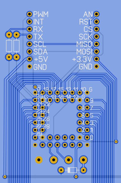 Craig Edited 2022-06-01 16:30 by Tinine |
||||
| Mixtel90 Guru Joined: 05/10/2019 Location: United KingdomPosts: 5711 |
IN------+--[ 1K ]----+------- PICO � � � �| � � � � � �| � � � ___ � � � � �___ � � �150R � � � � 430R � � � ___ � � � � �___ � � � �| � LINK � � | � � � �+--o �o �o---+ � � � � � � �| --------------+----------------- � �4-20mA � � � � � 0-10V PicoMite has LM4040 fitted, so range is 0-3V, 3V=20mA or 10V. Switch another 1K in parallel (or another 430R in series) and you get a 0-5V range too. 0.6V input corresponds to 4mA. Resistors should ideally be 0.1%. Edited 2022-06-01 16:52 by Mixtel90 Mick Zilog Inside! nascom.info for Nascom & Gemini Preliminary MMBasic docs & my PCB designs |
||||
| Volhout Guru Joined: 05/03/2018 Location: NetherlandsPosts: 3505 |
Hi MIck, This one is a bit over my head. I also think the picomite is not really a PLC. I know you can (in MMBasic) write some sequencer to make it perform like a PLC, but by using multiple picmites on the IO boards you easilly loose the typical PLC timing (unless you route a "SYNC" signal along all picomites, and implement a real time "update" from SYNC in each picomite (embedded in MMBasic ?). The essence of the PLC is that the SYNC presents an update moment, and a strict timing. When you connect a output to an input on a PLC, and program it with an inversion function between output and input, you will create an oscillator that runs at exactly half the SYNC frequency. This only works if you have strict latching of output and reading of input. The timing also allows creation of (PID) control algoritms. When the timing is not ensured, PID will never work reliable. So the only way I see a PLC running on a picomite is when the slaves (IO boards) are all under control of the main pico. The IO boards should not be timing critical (so 74HCT595/74hC164 shift register can work, but all under control of the one pico. The picomite essentially needs ONE important addition. It has to has a method to indication all PLC processed written in MMBasic execute within the SYNC cycle. This can be a simple LED connected to the "IDLE" DO:LOOP. As long as the LED is ON, all processes finish, when the LED turns off (no time is spend in the IDLE loop) the PLC becomes unreliable since the program did not perform all functions, but a new cycle is already started. What you have created may still be a viable product for some control applications, and many can have a lot of fun with it. But I would not use it in an industrial control application as is now. Edited 2022-06-01 18:54 by Volhout PicomiteVGA PETSCII ROBOTS |
||||
| Mixtel90 Guru Joined: 05/10/2019 Location: United KingdomPosts: 5711 |
It's not a "real" PLC, I know that. It could work in a similar way though. If each IO board runs a simple program that either copies it's inputs to a register or copies a register to it's outputs continuously then that's the basis. The master talks to each IO board in turn, reading and writing its register(s) into local ones then run through the program. Then it loops round and updates the local copies of the registers again. Communication with the boards uses the CS line as an interrupt to pull the board out of its loop to handle the SPI. As you say, everything should be synchronous, but in fact it wouldn't be. However, the program running in the master *does* see it as synchronous as there is no interruption for IO access. The actual delay caused by the local IO register update should be very short with only 9 SPI sequences to run, all of them short. The Siemens S5 used to use a serial interface, using shift registers in each IO module. That would have been very similar to serial SPI, program processing would stop while all the IO was read into the CPU. One thing this system *can* do, which is also found on some real PLCs, is to allow some autonomy of the IO boards. You can run things like fast counters, PWM ramps, level alarms etc. without slowing down the main program. Obviously, these use non-standard software on the individual IO board, but it's a possibility. On all the IO boards (except non-isolated digital in) the LEDs are independent of the IO, being controlled by the PicoMite. This means that they don't have to indicate one LED per channel. That gives more flexibility, you can have flashing LEDs for alarm inputs for example. TBH, if someone wanted a proper industrial control system then they wouldn't even consider this anyway, no matter how good it was. They usually want manufacturer support and don't mind paying for it. Not only that, but with a maximum capacity of 90 I/O (all basic digital) it simply isn't big enough for many users. Edited 2022-06-01 19:35 by Mixtel90 Mick Zilog Inside! nascom.info for Nascom & Gemini Preliminary MMBasic docs & my PCB designs |
||||
| Tinine Guru Joined: 30/03/2016 Location: United KingdomPosts: 1646 |
Dick Morley invented the PLC with the aim of creating something programmable that was familiar to the "click-clack" guys  This is 2022 and procedural programming is duck-soup The only thing wrong with your controller, Mick, is the name. It's a "Multi-Processor Controller" (MPC?) Granted, my PIDs require hard real-time (hence the Prop) but many don't. Try incrementing a variable on a 1ms SETTICK and sync it with a stopwatch and leave it for a few hours. Doesn't do too badly. I still prefer 4-wire, FD comm's though because it's essentially, infinitely expandable and with each node having its own intelligence, traffic can be kept to a minimum. The problem with the scanning PLC concept is that it continuously scans signals that are of no-interest  Craig |
||||
| Mixtel90 Guru Joined: 05/10/2019 Location: United KingdomPosts: 5711 |
All this scans is the IO register(s) for each board. It doesn't have to worry about mundane stuff like waiting for the ADC to be ready - the IO board does all that stuff. The name depends on how you use it, I suppose. :) In its basic form the IO boards are really only remote IO so I think it's fair to call it a PLC. After all, there aren't that many that only use relay ladder now. It's true that it's a MPC though as it doesn't have to be used like that. In fact CS could be a signal from the IO boards to say that they want to talk to the slave hub (previously called the master). It would be an asynchronous processing system then. I've not actually thought of a silly name for this one. The Mitey Ant 'cos it has a queen and a load of workers? Mick Zilog Inside! nascom.info for Nascom & Gemini Preliminary MMBasic docs & my PCB designs |
||||
| Tinine Guru Joined: 30/03/2016 Location: United KingdomPosts: 1646 |
A typical example for me is a clamping device. From fully open to fully closed is a distance of 100mm. This is a hydraulic cylinder. Fully opening only needs to happen in certain conditions and I reduce overall cycle time by pulsing the valve for a partial opening. This means setting an Open_Clamp output, waiting for the Clamp_Closed input to go low and then switching off the output after some milliseconds. For this, the master instructs the slave to "do it and let me know when done". The master doesn't need to be bothered with the specifics. How about Multi-Mitey? � Craig Edit: Or MultiMite Edited 2022-06-02 06:32 by Tinine |
||||
| Mixtel90 Guru Joined: 05/10/2019 Location: United KingdomPosts: 5711 |
Hmmmm... now there's a thought. :) A full size 9-slot board is now officially 100mm x 210mm. and a 3-slot is 100m x 96mm. I thought I might do my own buck converter to get the 5V simply because of reliability in getting components rather than modules. However, the easy to use through-hole switcher chips seem to be out of stock - apart from the now obsolete (and expensive on ebay) MCI4575-5.0_T. :( . Still, there's no rush. Mick Zilog Inside! nascom.info for Nascom & Gemini Preliminary MMBasic docs & my PCB designs |
||||
| Tinine Guru Joined: 30/03/2016 Location: United KingdomPosts: 1646 |
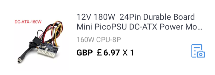 ATX Pico (how appropriate) is my preference. +5V +3V3 +12V -12V All fused. I have a version that takes 24V input and another that takes 12V � Craig Edited 2022-06-02 07:47 by Tinine |
||||
| Mixtel90 Guru Joined: 05/10/2019 Location: United KingdomPosts: 5711 |
I'm guessing that you are using a single output rail? It's obviously a switcher. The first thing, is there enough load on the line that is being monitored for voltage? Only one of the +ve outputs will be fed back to the feedback to try to stabilise all outputs. It's usually 5V, but it can be 3.3V. (However, the newer motherboards don't often use those rails and take all their supply at 12V, using local switchers on the motherboard where needed.) If the load on the monitored rail is very low then the supply can, in some cases, be a bit unstable. If you are using the +5 output then try loading 3.3V a bit and vice versa. You probably won't need a lot of load, try around 50mA-100mA or so. The miniature PSUs are almost always noisy. They rely on having a high switching frequency to reduce the size of any filtering components, which is fair enough, but in the effort to make everything as small as possible they sometimes skimp.You could try a bit of external RC filtering on the rail you are using. R will be needed to avoid too much capacitance on the output causing problems, but 0.5R or so may be OK. Also, they put noise on their supply rails, so make sure you have a good input cap as close as possible to it. It's usually 150-200kHz "hash" so bypass it with some low value ceramics. Don't go too big as the primary PSU might object. :) You could also try a ferrite ring or cable filter on the incoming cable to prevent radiation from it. Mick Zilog Inside! nascom.info for Nascom & Gemini Preliminary MMBasic docs & my PCB designs |
||||
| Tinine Guru Joined: 30/03/2016 Location: United KingdomPosts: 1646 |
You hit the nail on the head, Mick. This is the one thing that concerns me I want clean, stable power but am clueless regarding this. I come across trivial circuitry but the supply lines can have a slew of capacitors of various sizes. Real estate is available on my board (150mm X 400mm) so I don't mind overkill for this but I have no idea what I need to do. Is there a general guideline out there? Craig P.S. I have used these things to power the E-100 with my own motion control boards and they work perfectly. BUT those were emergency/panic jobs where I paid no attention to power quality. |
||||
| Mixtel90 Guru Joined: 05/10/2019 Location: United KingdomPosts: 5711 |
Do you want a single output supply? What current? I've been looking for one to get 5V at about 1.5A from a 24V (nominal) input. There are commercial modules that will do it, but most are a bit higher output than I need and all of them are too expensive for my purposes. At the other end are the Chinese modules, but you can't guarantee any quality or that they'll be available for any length of time. That's why I've been looking at building my own using a TO220 switcher with a couple of capacitors, a diode and an inductor. The problem with that is availability at the moment. If you want more output current then you can use a switcher chip with external power device(s). These "simple switcher" things are all very similar. The main difference is that some are fixed voltage and some variable using a resistor or two. You may be able to clean up the output from that supply. A scope will help in this as you really need to load the supply and watch what happens. First - make sure you have plenty of available current input. Those things can draw up to 20A from the incoming supply if fully loaded. If they run short of current they are liable to shut down-startup-shut down etc. If your incoming supply hasn't got a filter on the lead near the plug then put a few turns through a ferrite ring to stop radiation from the incoming wiring. Watch your grounding. Don't put low current signals through the same conductor as a high current supply. They should only meet at one point - the output from the switcher. If you want the 3.3V rail then you can use a LDO regulator from the 5V output. That will act as a remarkably good filter. The higher the PSSR value the better in this case. You can try a RC filter on the output, but the resistor will drop some voltage so it will have to be low. The higher it is the bigger the capacitor that can follow it. You can't usually just slap another cap straight on the output of a switcher. I'd start with about 0.5R and 1000uF and see what happens. It shouldn't stop the PSU from starting up. If it does then reduce C until it does. After that it depends on how much voltage you can afford to lose in R. The higher its value the better the filter, but the less voltage you have and the less stable it is. :) It's possible to use a LC filter, but much trickier as you need to take the frequency of the switcher into consideration as well as the load current. It's not something I'd normally attempt but the results would be far better than a RC filter. Mick Zilog Inside! nascom.info for Nascom & Gemini Preliminary MMBasic docs & my PCB designs |
||||
| Tinine Guru Joined: 30/03/2016 Location: United KingdomPosts: 1646 |
Well, the reason for choosing the supply is that I need: +5V for the Prop and external incremental encoders. For the time being, I'm also stuck with a few 5V devices due to availability. +3V3 for four Picomites (disabled on board SMPS) +/- 12V for my +/- 10V analogue motor command signals. The incoming supply to this ATX Pico module is DC from a linear PSU. Craig Edited 2022-06-02 21:53 by Tinine |
||||
| Mixtel90 Guru Joined: 05/10/2019 Location: United KingdomPosts: 5711 |
TBH I'm surprised that it's messing up USB. That type of PSU is used a lot for the little motherboards now - all of them with USB. :) It might be worth putting a scope on. I know some can be noisy, but surely not *that* noisy. Have you tried substituting a standard PC power supply as a test? (I thought you'd be on the park today. :) ) Mick Zilog Inside! nascom.info for Nascom & Gemini Preliminary MMBasic docs & my PCB designs |
||||
| Tinine Guru Joined: 30/03/2016 Location: United KingdomPosts: 1646 |
Oh, a bit of a mix-up (no pun )No, the PSU that (definitely) messes up my USB is another. It's one of those that resembles a laptop power supply but has a knob/switch on top. It's variable from 3.3V to 24.5V....I have done away with it. Replaced it with something that is similar but with a switch selectable output and this one is fine No, this is unrelated to the ATX Pico topic. Weird though....I would investigate but can't be bothered right now. Just relieved that it wasn't something more serious Craig |
||||
| Tinine Guru Joined: 30/03/2016 Location: United KingdomPosts: 1646 |
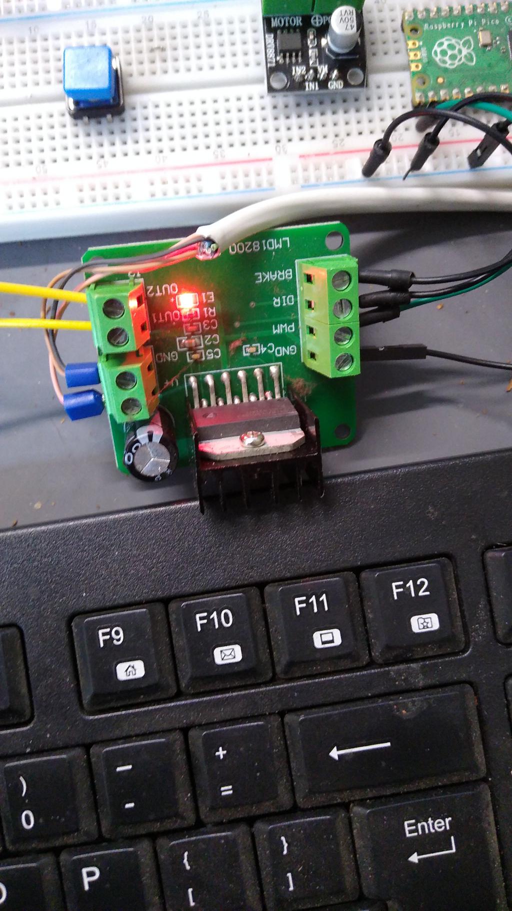 I'm messing with the seat-heater that we discussed elsewhere. Using the Picomite PWM to drive a LMD18200. Every time I would try to change the PWM value from the terminal, the USB would be dead. Everything is hunky dory with the other PSU |
||||
| Page 1 of 5 |
|||||
