
|
|
Forum Index : Microcontroller and PC projects : PicoMite PLC project
| Author | Message | ||||
| Tinine Guru Joined: 30/03/2016 Location: United KingdomPosts: 1646 |
 How small did you go? How small did you go?The serial port thing: Presumably you'd be doing a 485/422 thing, no matter what? I realise that pins are precious but the drivers have enables, right? Select one or the other as required? Craig |
||||
| Mixtel90 Guru Joined: 05/10/2019 Location: United KingdomPosts: 5705 |
The holes are generally 0.72mm and need about 0.8mm minimum. Not good drilling out PTH as you then need to solder both sides - not possible underneath a connector. On the system as it stands, no. The main bus would use simple pin to pin UART connection unless I can get SPI to work. It doesn't leave the board - only 200mm lines. At the moment there is no facility for any external serial port at all. The master has no spare COM ports if I have to use one for the bus. Mick Zilog Inside! nascom.info for Nascom & Gemini Preliminary MMBasic docs & my PCB designs |
||||
| Tinine Guru Joined: 30/03/2016 Location: United KingdomPosts: 1646 |
Daisy-chained or using the diode multi-drop method (I have gone with diode multi-drop after extensive testing)? Craig |
||||
| Mixtel90 Guru Joined: 05/10/2019 Location: United KingdomPosts: 5705 |
Undecided. Probably multidrop of some sort. Not easy trying to find where to put the diodes! Ideally I want to use SPI. Edited 2022-06-09 05:51 by Mixtel90 Mick Zilog Inside! nascom.info for Nascom & Gemini Preliminary MMBasic docs & my PCB designs |
||||
| Tinine Guru Joined: 30/03/2016 Location: United KingdomPosts: 1646 |
One of the cool things with multi-drop serial (for me): -Header Byte -Address Byte -Command Byte -Data Bytes -Checksum If the Address Byte = FF, this means all slaves need to act (broadcast). One can also have groups, based on Addresses. I realise that zipping through a bunch of CS' is a mere blip but you'll also need to send data to each one, no? Craig |
||||
| Mixtel90 Guru Joined: 05/10/2019 Location: United KingdomPosts: 5705 |
Just CS lines. If I want to broadcast I can just set them all and transmit. I don't want card addresses, I want to be able to just pull one out and pkug in a replacement of the same type and it'll work. Consequently all the IO boards have CS on the same pin and the base takes care of distributing the signals from pins on the master. Mick Zilog Inside! nascom.info for Nascom & Gemini Preliminary MMBasic docs & my PCB designs |
||||
| Tinine Guru Joined: 30/03/2016 Location: United KingdomPosts: 1646 |
I don't know enough about SPI...they all don't need to dish-out something on MISO or is that down to the programmer? Craig |
||||
| Mixtel90 Guru Joined: 05/10/2019 Location: United KingdomPosts: 5705 |
Up to the programmer. I *think* the spec works like this: The master drops the CS line to wake up the slave The master then clocks out a number of bytes: ..The data is valid on MOSI on the rising edge of the clock ..The MISO line is read on the falling edge of the clock After that the master continues to clock out zeros or junk for the number of additional bytes that it is expecting from the slave. The slave will dump what it doesn't need. The master then raises CS to end the communication. It has now sent its TX buffer and received what the slave had waiting for it. If you aren't bothered about receiving data just dump it. The slave will send it anyway. Only the master can send the clock and the slave has to follow its edges, so it's completely synchronous. Mick Zilog Inside! nascom.info for Nascom & Gemini Preliminary MMBasic docs & my PCB designs |
||||
| Mixtel90 Guru Joined: 05/10/2019 Location: United KingdomPosts: 5705 |
Just been playing with the design of a serial interface board. As I might be using COM2 for the UART bus, I've multiplexed COM2 into two ports, using a GP pin to switch between them. One port is RS-422 5V (4-wire) as I know Craig likes these. :) The other port has parallel connected connections: RS-232 5V and RS-485 half-duplex 5V. The RS-232 has an AUX terminal, which is switched by the same signal as the RS-485 DE/RE. I'm not sure exactly what this board could be used for as it's a serial interface on the end of a serial interface, but there must be something. :) At the very least it could probably have a HMI hung off it (although the master has bluetooth now). ============================ EDIT: And now, a "sea of holes" board that includes the following: .. A plug-in PicoMite .. 10-way plug-in terminal block .. Connectors for the base board - with the standard PicoMite pins connected .. 5 LEDs on GP0-GP4 .. No ground plane on eithe side of most of the user area .. No holes specifically dedicate to GND or supplies - that's up to the user. If I include them they *will* be in an inconvenient place for someone. :) Edited 2022-06-10 19:49 by Mixtel90 Mick Zilog Inside! nascom.info for Nascom & Gemini Preliminary MMBasic docs & my PCB designs |
||||
| Mixtel90 Guru Joined: 05/10/2019 Location: United KingdomPosts: 5705 |
This isn't dead yet. :) I've made changes which should allow a development system to be produced easily. 1. The base has changed, allowing the Master to be connected to the bus as either a SPI or a UART system. This is done by soldering a couple of wire links in, so those could be pluggable on a development system. The Master would have the required pull-up resistor on a UART system. 2. The "sea of holes" board is more sophisticated now (and is called the "development module". The LEDs are gone, to give more usable area. There *are* some power and GND holes now, but they shouldn't be in the way. Pins on the PicoMite are connected to the adjacent holes both outside and inside the socket area, so are easy to put resistors, for example, directly onto the pins or to probe them. The board can, with not too much messing about, be made into a Master, although it would need a bit of wiring to use it for a full bus as 9 wires have to cross the Picomite from one side to the other if you want to do it properly. It should now be possible to chop the base into a 3-slot board very easily. Then you could order just 3-slot boards (98mm x 100mm) and development modules (100mm x 100mm for two) to start playing. You would get 5 bases and 10 development modules (after sawing them up). Initially I'd simply power the main bus at 5V instead of 24V and link it on the Master instead of having a 5V regulator. It only affects the I/O and makes it much easier to mess with. To make this nice and easy, the base can now accept a 3.5mm barrel jack for power, together with a local electrolytic capacitor. These are fitted in the area normally used for the base terminals. You lose the terminal for the /Fault output, but that's are of little use in the initial stages and you can always dangle a LED and resistor if you need it. A fully equipped dev system would have one master and three slave boards, so you'd have enough PCBs to make two full systems, with 3 spare bases and a couple of spare slaves. If there's any interest I'll post pictures/files/whatever for this basic system, although I've not done any schematics or documentation yet and things may still change. The initial idea would be to get the master-slave comms working, with no real need for I/O apart from putting some LEDs on to monitor what's happening. With the comms working certain protocols have to be sorted out, such as slave scanning on boot and the slaves returning their type and number of registers etc. so that the master knows how to use them. I envision this as being a set of standard SUB and Function blocks, a set for masters and a set for slaves - no matter what type. This would give a standard framework to be used for building a complete system. Mick Zilog Inside! nascom.info for Nascom & Gemini Preliminary MMBasic docs & my PCB designs |
||||
| bigfix Senior Member Joined: 20/02/2014 Location: AustriaPosts: 124 |
There will be a commercial product based on RP2040 - with a commercial price... Iono RP D16 The doc is not yet available, but maybe interesting how they interface in an industrial environment However, the Maxim chips which are described in this article, are very tiny SMD... Edited 2022-06-21 22:51 by bigfix |
||||
| Tinine Guru Joined: 30/03/2016 Location: United KingdomPosts: 1646 |
Mick, Just thinking about the 100 X 100 constraints. I'm really liking this P2-Edge concept. Don't know if it will work for your format but this is 80-pins. My first thought was two PGA2040s on one of these boards. Would be even better to start from scratch and build the 2040s right on to the board, though   Craig Edit: I guess this thinking into the box Edited 2022-06-21 23:04 by Tinine |
||||
| Tinine Guru Joined: 30/03/2016 Location: United KingdomPosts: 1646 |
Here we go again; "industrial" but with current-sinking outputs? Who uses current-sinking outside of a PCB? I have never come across it �  Oops....read it wrong....it's actually high-side  Craig Edited 2022-06-21 23:19 by Tinine |
||||
| Mixtel90 Guru Joined: 05/10/2019 Location: United KingdomPosts: 5705 |
Pretty, but I'm not in competition with them. :) �This is for *my* entertainment. lol Why use another board when my design is better, more flexible and cheaper, Craig? �:) The base can have up to 9 slots for I/O modules plus the master. 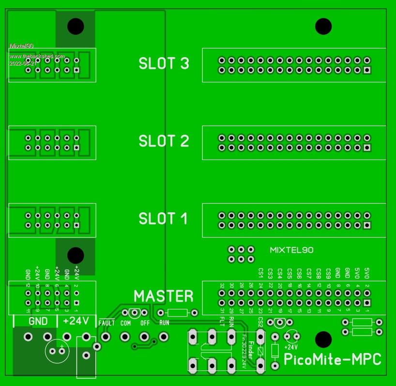 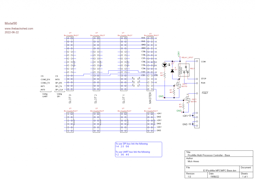 Typically two I/O modules or masters fit onto a single 100x100 board. Cut them afterwards. 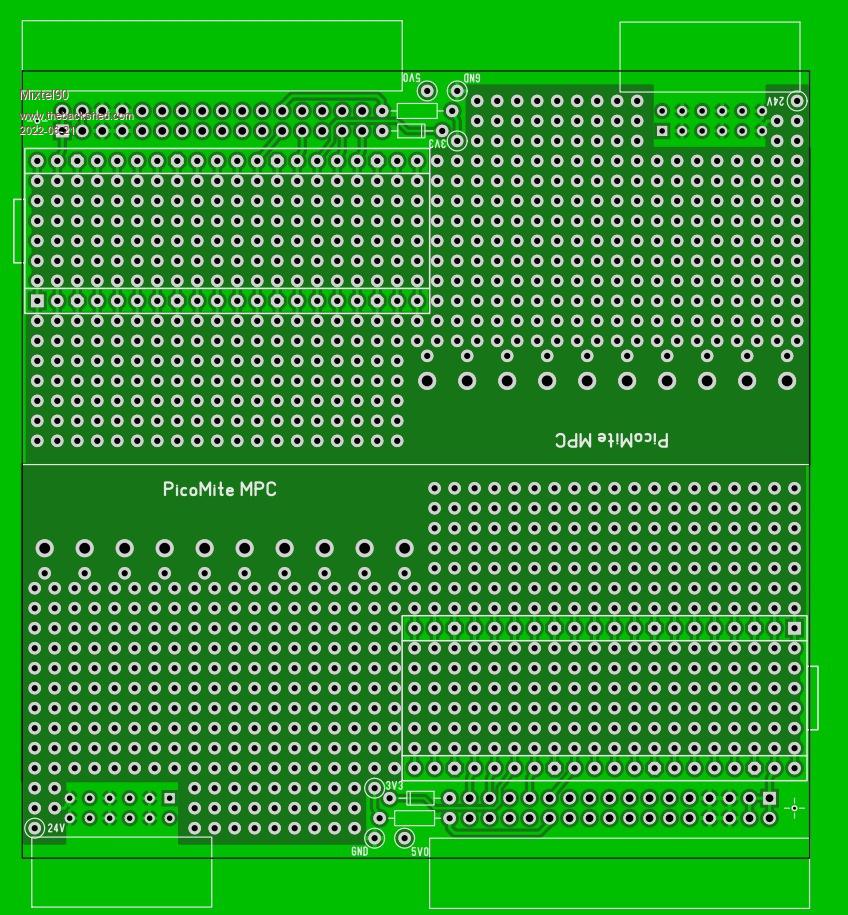 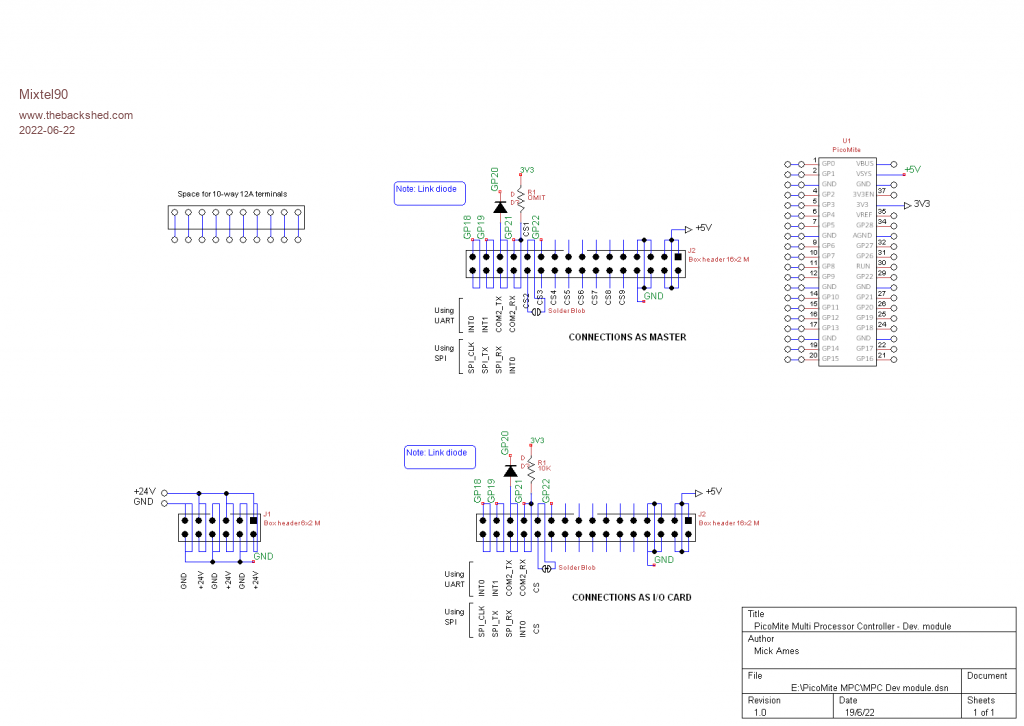 This is a master module circuit. I've done the board layout, but still a little undecided on how to lay out the reg and filter components. 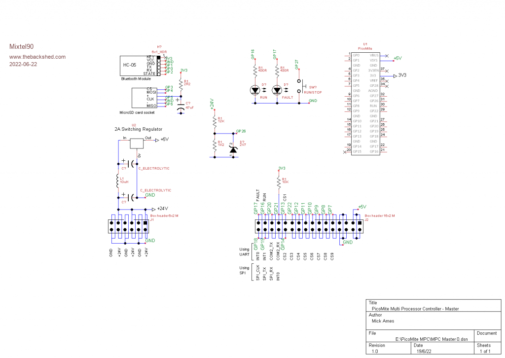 Edited 2022-06-22 00:20 by Mixtel90 Mick Zilog Inside! nascom.info for Nascom & Gemini Preliminary MMBasic docs & my PCB designs |
||||
| Tinine Guru Joined: 30/03/2016 Location: United KingdomPosts: 1646 |
I have this on my serial network. On power-up, all addresses are zero but each node has an input 'Addr_in' and an output 'Addr_out'. 1st node has its Addr_in permanently high. First address is broadcast and this node takes it and sets its Addr_out high which feeds the Addr_in of node #2 which then takes the next broadcast address. Works well but considering the fact that swapping-out a module is rare, I prefer to use the pins as regular I/O. Craig |
||||
| Mixtel90 Guru Joined: 05/10/2019 Location: United KingdomPosts: 5705 |
My idea is that on boot a standard routine in the master will scan the I/O boards to see what it has. Each board will return its type and how many registers it will require for talking to the master. This info will be compared with a list of I/O boards provided as part of the user program. The master will refuse to start if any board is wrong or missing. The register numbers are required if using SPI, as some boards may only need one or two command registers yet return a lot more values. Others may require a lot of setup info yet only return "Done" or "Fault number n". I could have had many more I/O boards, but not within a sensible size. I'd already decided that the maximum length would never exceed about 200mm - it ended up at 210mm using a nice easy 20mm board spacing. :) Using SPI I'd need a CS pin for each board anyway, so 9 boards fits nicely. Edited 2022-06-22 00:34 by Mixtel90 Mick Zilog Inside! nascom.info for Nascom & Gemini Preliminary MMBasic docs & my PCB designs |
||||
| Tinine Guru Joined: 30/03/2016 Location: United KingdomPosts: 1646 |
I hope you get around to testing this concept....We need more industrial control projects and the PicoMites are ideal for this. SPI is a non-starter for me but I wanna see it work. Once you have intelligence at the node, network traffic can be next-to-nothing and the first thing to bite you is that the end-user needs one more input When using COTS (commercial off the shelf) products, how many times did I have to cough up 500 bucks for an extra input  Craig |
||||
| Mixtel90 Guru Joined: 05/10/2019 Location: United KingdomPosts: 5705 |
I made the system to work with either a UART or an SPI bus interface. I figured that if I made it SPI only and then discovered that it wouldn't work then I'd have scrap boards. :) It cost me a connector pin and a bit of jiggery pokery, but it should work. You don't have to use CS either if you are using UART, but you need to give the IO boards addresses then. In theory the dev board can be configured as a cut-down master, so it's feasible to just order 5 of each of those and the 3-slot base for experimenting. It'll cost as much for the connectors - and you need a few PicoMites too, of course. If you really wanted to you could easily reduce this to just a couple of boards, but I don't think I'd consider that unless space was seriously tight. You could even run the master on its own (with something to bring the pins out to terminals) but it's a bit short of IO pins. Mick Zilog Inside! nascom.info for Nascom & Gemini Preliminary MMBasic docs & my PCB designs |
||||
| Tinine Guru Joined: 30/03/2016 Location: United KingdomPosts: 1646 |
Sooo much potential here with the Picomite. I haven't done this but I will at some point: Distributed control where COM1 talks to the master. COM2 configured as the console and each one has, for example, a HC05. The Picomite slaves take care of local processing and simply report to the master. The programmer connects to the slave via BT to develop the code for the local tasks. Your client could even run TeamViewer on his phone enabling you to hook up remotely to modify the code. Yeah I get carried away Craig |
||||
| Tinine Guru Joined: 30/03/2016 Location: United KingdomPosts: 1646 |
For giggles, Trapezoidal Motion Profile runs at a very respectable 180 uSecs on Picomite warp-speed. Heck, if we can get quadrature decode/counting from the PIO, we'll have the world's first PLC with proper motion control (that I'm aware of) in interpreted BASIC  Looped 1000 X Dim integer Velocity, Ac, Dc, Sp, MoveR Dim integer Da, Dd, Ds, Accel, Decel, Triang Dim integer Ta, Td, Ts do while inkey$ <>"":loop 'Accel = Sp / Ta 'Decel = Speed / Td timer = 0 for i% = 1 to 1000 Velocity = 300000 'quadrature encoder counts/sec Sp = Velocity*1000 Accel = 1200000 'quadrature encoder counts/sec/sec Ac = Accel Decel = 1500000 'quadrature encoder counts/sec/sec Dc = Decel MoveR = 1219311 'distance to move in quadrature encoder counts Ta = (Sp / Ac) Td = (Sp / Dc) sp = velocity Da = ((Ta * Sp)/2000) Dd = ((Td * Sp)/2000) Ds = 0 'Print "Distance to accel", Da 'Print "Distance to decel", Dd If (Da + Dd) > MoveR Then 'No slew so make a triangle Triang = ((Da + Dd) - MoveR)>>1 Da = Da - Triang Dd = Dd - Triang Else Ds = MoveR - (Da + Dd) Ts = (Ds*1000) / Sp End If next print "T=: "; timer Print "Time to accel", Ta Print "Distance to accel", Da Print "Slew Time", Ts Print "Slew distance", Ds Print "Time to decel", Td Print "Distance to decel", Dd Print "Total Move", Da + Ds + Dd Craig |
||||
