
|
|
Forum Index : Microcontroller and PC projects : [Electronics] 555 Monostable test
| Page 1 of 2 |
|||||
| Author | Message | ||||
| thwill Guru Joined: 16/09/2019 Location: United KingdomPosts: 3839 |
Hi folks, This should really be in the "Electronics" forum but my experience is that because it is a beginner question and isn't about Inverters it will get ignored. Perhaps you will tolerate it here and someone can help me out. I'm playing with a 555 timer in monostable mode: 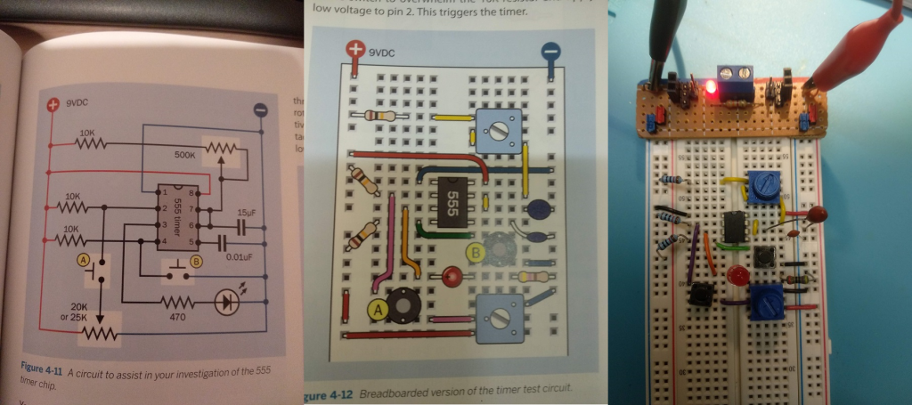 Note intentional differences between diagram and actual breadboard - I'm taking advantage of the fact my breadboard has two power buses to avoid some of the longer hookup wires. It all seems to work as described except that one of the tests in my text book is "Get out your meter, set it to measure DC volts, and measure the voltage between pin 2 and negative ground while you adjust the 20K trimmer to various settings and press button A. I'm betting that when you press the button to a apply a voltage below 3 volts to pin �2, the timer will falsh the LED. Above 3 volts, I doubt that anything will happen." What I'm finding is that connecting the probes to measure the voltage is triggering the LED pulse without button A being pressed. Any ideas ? Best wishes, Tom Edited 2022-06-24 07:35 by thwill Game*Mite, CMM2 Welcome Tape, Creaky old text adventures |
||||
TassyJim Guru Joined: 07/08/2011 Location: AustraliaPosts: 5902 |
1. The meter is set to amps instead of volts, 2. The 10k resistor from V+ to pin 2 is not making connection or much higher than 10k (such as 10M) You should get a reading on the meter even if the led is triggered. Jim VK7JH MMedit MMBasic Help |
||||
vegipete Guru Joined: 29/01/2013 Location: CanadaPosts: 1082 |
Show us your voltmeter. Visit Vegipete's *Mite Library for cool programs. |
||||
bigmik Guru Joined: 20/06/2011 Location: AustraliaPosts: 2870 |
Hi Tom, Are you using an old analog voltmeter by chance? They usually have something like 10k-20k ohm/volt internal resistance in volts mode so if set to 5v you will get 100k resistance in the meter. Using a modern digital usually have a minimum internal resistance of 10MegOhm Regards, Mick Mick's uMite Stuff can be found >>> HERE (Kindly hosted by Dontronics) <<< |
||||
| Turbo46 Guru Joined: 24/12/2017 Location: AustraliaPosts: 1593 |
Do you measure 9 volts on pin 2? If not the resistor in not making contact. Try re- connecting it. You may have the meter on the incorrect range (ie. current) even an analogue meter shouldn't drag the pin 2 voltage down below 3 volts if the resistor is correct and making contact in the breadboard. There shouldn't be enough capacitance in the voltmeter to momentarily drop the pin 2 voltage but if all else is OK then try connecting the voltmeter before powering up the circuit. Bill Keep safe. Live long and prosper. |
||||
| panky Guru Joined: 02/10/2012 Location: AustraliaPosts: 1094 |
Your 470ohm resistor appears ?? to be connected wrong - looks like the left end is one hole right of where it should be? �Picture not quite clear enough to be sure although this shouldn't make any difference. Doug. Edited 2022-06-24 10:24 by panky ... almost all of the Maximites, the MicromMites, the MM Extremes, the ArmMites, the PicoMite and loving it! |
||||
lew247 Guru Joined: 23/12/2015 Location: United KingdomPosts: 1676 |
Your 470 ohm resistor is the wrong side of the LED Swap them around and make certain your led is the correct way around or it won't work the way you want it to  |
||||
| Mixtel90 Guru Joined: 05/10/2019 Location: United KingdomPosts: 5725 |
I used to love playing with the 555 - and it still has its place. Pity it's almost as cheap to use an 8-pin microcontroller now, by the time you've also paid for resistors and capacitors. Does anyone still do unijunctions now? Mick Zilog Inside! nascom.info for Nascom & Gemini Preliminary MMBasic docs & my PCB designs |
||||
| Turbo46 Guru Joined: 24/12/2017 Location: AustraliaPosts: 1593 |
The location of the LED and the 470 ohm resistor appear to be reversed on the breadboard but apart from that the circuit looks correct to me. It's hard to tell but it looks like the flat (cathode) is on the right (negative) side going to the 470 ohm resistor which is connected to the negative supply. Tom is seeing the circuit triggering so I am guessing that that part of the circuit is working. Even if it were wrong, it would not affect the triggering. Please refer to my post above. Bill Keep safe. Live long and prosper. |
||||
| thwill Guru Joined: 16/09/2019 Location: United KingdomPosts: 3839 |
Hi folks, See additional photos. 1. I have the meter set correctly (20V DC range) - famous last words. 2. Same behaviour with both my (digital) meters: Duratool D03144 and Mercury MTB01. 3. The resistors all read correctly and are making contact. 4. Behaviour is same whether 470R resistor is "before" or "after" the LED - should that even matter, doesn't it current limit either way? Note that the schematic and diagram in the book actually show it two different ways. 5. I do know how to wire up an LED ;-) though I have been known to serial blow them when testing them without remembering to add a current limiting resistor. 6. Voltage on pin 2 is "correct" and controlled by the 20K trim as expected. EDIT: You also get a pulse if powering up after connecting the multimeter. And also a pulse when disconnecting the multimeter ... but that might be "bounce" I suppose caused by briefly breaking and then making contact whilst disconnecting. Basically everything appears to work as expected except that connecting the multimeter (+ve to pin 2 and -ve to ground) causes a single immediate pulse which AFAIK means it is briefly sending pin 2 low, but not maintaining it low ? 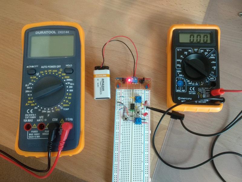  Best wishes, Tom Edited 2022-06-24 21:35 by thwill Game*Mite, CMM2 Welcome Tape, Creaky old text adventures |
||||
| Mixtel90 Guru Joined: 05/10/2019 Location: United KingdomPosts: 5725 |
Part way down this page there is a diagram of the internals of the 555. If you look, the Threshold input has your timing resistor, timing capacitor and Discharge transistor on it. The Trigger input is normally pulled high by a 10k resistor. If Trigger drops below 1/3 VCC then the bottom comparator triggers, flips the flip-flop and turns off the Discharge transistor. That allows the timing capacitor to charge. When the capacitor charges to 2/3 VCC the top comparator triggers. This flips the flip-flop back again, discharging the timing capacitor. Anything that pulls the Trigger input below 1/3 VCC will trigger the monostable. This could be the internal resistance of a multimeter. It's important that the pull-up resistor makes good contact otherwise you'll get unreliable triggering. Mick Zilog Inside! nascom.info for Nascom & Gemini Preliminary MMBasic docs & my PCB designs |
||||
| phil99 Guru Joined: 11/02/2018 Location: AustraliaPosts: 1781 |
Is the pullup resistor on pin 4 (reset) making good contact? Check that you have Vcc on pin 4. If it is less than Vcc-0.6V it will be held in the reset state (for most versions, for some brands the reset point is 0.6V above Gnd). Edit Wasn't the reason for this to test some tantalums? You could write a charge / discharge program to measure the time constant with a known resistance. . Edited 2022-06-24 22:37 by phil99 |
||||
| thwill Guru Joined: 16/09/2019 Location: United KingdomPosts: 3839 |
I have Vcc on pin 4. Thanks, Tom Game*Mite, CMM2 Welcome Tape, Creaky old text adventures |
||||
| Mixtel90 Guru Joined: 05/10/2019 Location: United KingdomPosts: 5725 |
Tom's playing. :) He only needed an astable to flash an LED repeatedly for a while to test the capacitors. He's obviously got bitten by the 555 bug. lol Mick Zilog Inside! nascom.info for Nascom & Gemini Preliminary MMBasic docs & my PCB designs |
||||
| thwill Guru Joined: 16/09/2019 Location: United KingdomPosts: 3839 |
Yes, I'm playing, I decided to take a brief sojourn back to my text books and fill in some of the gaping holes in my basic understanding. The thing about micro-controllers and especially with MMBasic is you can achieve a hell of a lot without really knowing what you are doing electronically ... I'd like one day to know what I'm doing. Best wishes, Tom Game*Mite, CMM2 Welcome Tape, Creaky old text adventures |
||||
| Mixtel90 Guru Joined: 05/10/2019 Location: United KingdomPosts: 5725 |
That's very commendable. :) It does no harm at all to understand some of the hardware side. Mick Zilog Inside! nascom.info for Nascom & Gemini Preliminary MMBasic docs & my PCB designs |
||||
| Turbo46 Guru Joined: 24/12/2017 Location: AustraliaPosts: 1593 |
Hi Tom, it seems as though you have everything correct. It just appears that the trigger input is more susceptible to 'noise' that we would expect. I would not worry about it and move on. Remember that test instruments can affect the circuit that you are testing. Probe around in an active audio amplifier and you will hear lots of clicks and pops, it's the same thing here. It's probably better to connect the voltmeter to the pot side of switch 'A' and measure the test voltage as you adjust the pot. Note that the 10k pullup on pin 2 will be in parallel with the top part of the pot when the switch is closed so it may modify the voltage when you push the button. See here for a simple 555 oscillator. Bill Keep safe. Live long and prosper. |
||||
| TassyJim Guru Joined: 07/08/2011 Location: AustraliaPosts: 5902 |
Put a capacitor or two across the 9V supply. A 0.1 or 0.01uF and a 1-10uF. The 0.01/0.1 are for HF spike reduction and the 1-10uF is to get rid of the high internal impedance of the 9V battery. With digital circuits, the usual rule is to put a 0.1uF at every IC. Jim VK7JH MMedit MMBasic Help |
||||
| phil99 Guru Joined: 11/02/2018 Location: AustraliaPosts: 1781 |
"Put a capacitor or two across the 9V supply." The stripboard module has plenty of room for permanent additions, as well as adding one close to the 555. A 10nF to Gnd. on pin 2 might also be useful in reducing sensitivity to noise. Mains hum pervades everything and the meter leads make a good antenna for it. |
||||
| tgerbic Newbie Joined: 25/07/2019 Location: United StatesPosts: 40 |
thwill, What book are you using? I decided to build the circuit up and capture the traces, just for the fun of it. Pin 5 shows the threshold voltage of 3V (VCC/3). The upper trace is pin 3, which goes high when triggered, then low based on charge time controlled by the 500K pot. The second trace is pins 6 and 7 which shows the timer charging The third trace shows the high pull-up being pulled down to <3V causing the triggering. The fourth trace shows the trigger voltage set by the 20K pot being applied to pin 2 (when pushbutton is pressed) which pulls pin 2 down to <3V. 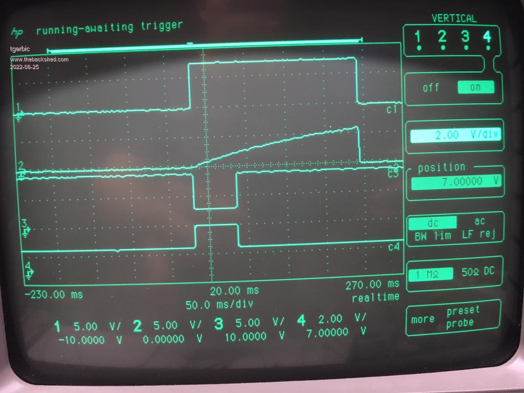 As expected as you vary the 20K trigger voltage above 3V and below 3V, the timer will trigger. Now here is what I found interesting. I used my Fluke 45 DMM to measure the voltage at pin 2. Each time I touched the positive lead to pin 2 the circuit would trigger. Further investigation showed that this did not happen if I used a 10M resistor in place of the DMM, assuming the DMM presented 10M when it touched pin 2. Hmmmm... I found if I used a resistor lower than 4.5K the circuit would trigger just like touching the DMM positive lead. However this cannot be it. Next test was to try an analog meter. I tried using my Heathkit IM-25 and an HP 410C in place of the DMM and neither triggered the timer. Interesting that a digital meter would trigger the circuit but an analog meter would not. Perhaps this may be related to the auto range mechanism in the digital DMM or input capacitance? Further examination of the signal on pin 2 shows when the DMM lead is touched to the pin the voltage can drop all the way to zero, and sometimes below??, for some pico seconds (below the trigger threshold for nearly a microsecond). Checking the schematic I can see a 100pf cap to ground in the middle of the DC volt path to the Analog Processor IC. I suspect that is causing it as I cannot see any other capacitive component in the path. 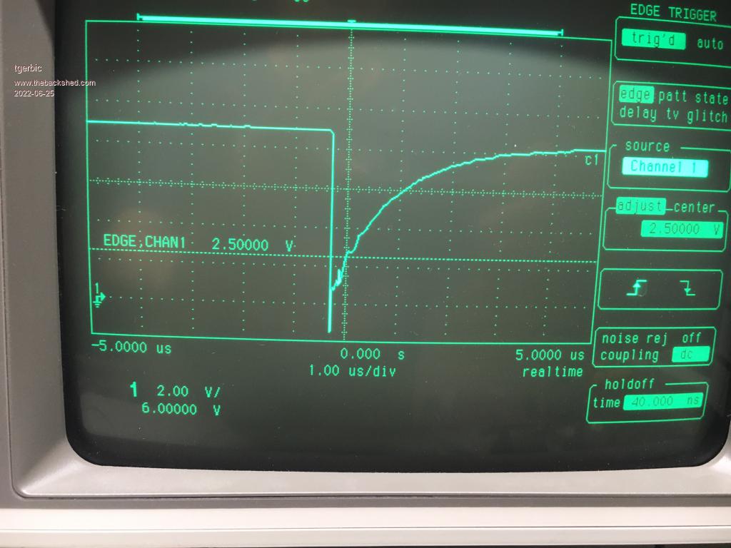 This is where the false triggering is coming from. Welcome to the fun world of hardware design and troubleshooting. Never completely trust your test equipment. Yet another example of a difference between analog voltmeters and DMMs, or electronics theory and practice. Tony |
||||
| Page 1 of 2 |
|||||
