
|
|
Forum Index : Microcontroller and PC projects : [Electronics] 555 Monostable test
| Author | Message | ||||
| circuit Senior Member Joined: 10/01/2016 Location: United KingdomPosts: 231 |
Your textbook looks most interesting - what textbook is it? |
||||
| Mixtel90 Guru Joined: 05/10/2019 Location: United KingdomPosts: 5726 |
@Tony: That was extremely interesting! Thanks. As you say, you can never be entirely sure that what your instruments are telling you is the whole truth. Mick Zilog Inside! nascom.info for Nascom & Gemini Preliminary MMBasic docs & my PCB designs |
||||
| phil99 Guru Joined: 11/02/2018 Location: AustraliaPosts: 1783 |
A 10nF to 100nF between pins 1 & 2 should overcome the problem. |
||||
| lizby Guru Joined: 17/05/2016 Location: United StatesPosts: 3015 |
Tony--thanks very much for those shots and that explanation. Tom--you see what mysteries within mysteries you get into when you stray from the true path of zeroes and ones. I try never to. PicoMite, Armmite F4, SensorKits, MMBasic Hardware, Games, etc. on fruitoftheshed |
||||
| thwill Guru Joined: 16/09/2019 Location: United KingdomPosts: 3841 |
Hi folks, Thanks for all the assistance, especially to Tony who went "above and beyond". You lost me, what were the other end of these 10M and 4.5K resistors attached to? Assuming you aren't just waving isolated resistors in the air like magic wands - I tried that and was glad to see nothing happened, if it had then I might have sworn off electronics for good  . .- The book I'm learning electronics from is "Make: Electronics" by Charles Platt � (ISBN 978-1-680-45026-2) which is VERY clearly illustrated and AFAIK accurate; though as a � beginner text I'm suprised he didn't mention that this issue might be present for this � particualr exercise, even though he might need to gloss over the details. I have the 2nd Edition, � I believe there is a 3rd Edition now. - A (nominally) 100nF cap between pins 1 & 2 fixed the problem. - I also built the 555 oscillator linked by Turbo64 and tested my suspect 22uF tantalums, � 20% of them wouldn't "oscillate" and are now in the bin. - I'm now moving on. I have my PicoGAME constructed (with a shiny new tantalum rather than one of � the suspects) and I need to integrate controller support and finish my game. Thanks again, Tom Edited 2022-06-26 01:29 by thwill Game*Mite, CMM2 Welcome Tape, Creaky old text adventures |
||||
TassyJim Guru Joined: 07/08/2011 Location: AustraliaPosts: 5904 |
Every meter puts some load on the circuit when you connect it. A typical digital multimeter will have the same effect as putting a 10 meg resistor, in this case between pin 2 and ground. An old style analogue meter will have much lower resistance. You can place a resistor from pin 2 to ground to test the effect of various meters. There is also some capacitance which we (and the specification data for the multimeters) tend to ignore. Even a small capacitor looks like a short circuit until it gets charged up and it was this capacitance 'short' that was briefly pulling pin 2 down to ground when you applied the meter. Putting a capacitor that is much larger than the meters capacitance at pin 2 allows the stored charge of the capacitor to be used to charge the meters capacitor without bringing the pin level down too low. Now I am going to measure the capacitance on my meters. I know my main meter specifies 50pF but that is only for the capacitance ranges. It is silent for the other settings. Does that confuse you even more? Jim VK7JH MMedit MMBasic Help |
||||
| Turbo46 Guru Joined: 24/12/2017 Location: AustraliaPosts: 1593 |
Here is a partial circuit for a DMM input. Notice the 'compensation' capacitors used to flatten the frequency response for the AC ranges. They would be causing the triggering of the 555. 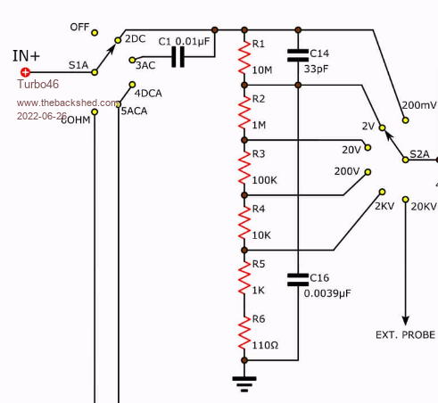 Test instruments can affect the circuit that you are testing. Bill Keep safe. Live long and prosper. |
||||
| phil99 Guru Joined: 11/02/2018 Location: AustraliaPosts: 1783 |
Much of the above is about the problem of triggering on transients. Below is an example of where you want it to trigger on transients. The local fire brigade was building up a large trailer mounted diesel pump and wanted something more than just the usual engine warning lights. The idea I came up with was to put an inductor in series with the supply to the engine fault lamps. When ever there is a sudden increase in current the transient produced by the inductor triggers and latches a 555. A mute button resets it, ready for the next fault. Another 555 pulses a horn and the Water Point beacon (no matter whether the beacon is switched on or off). 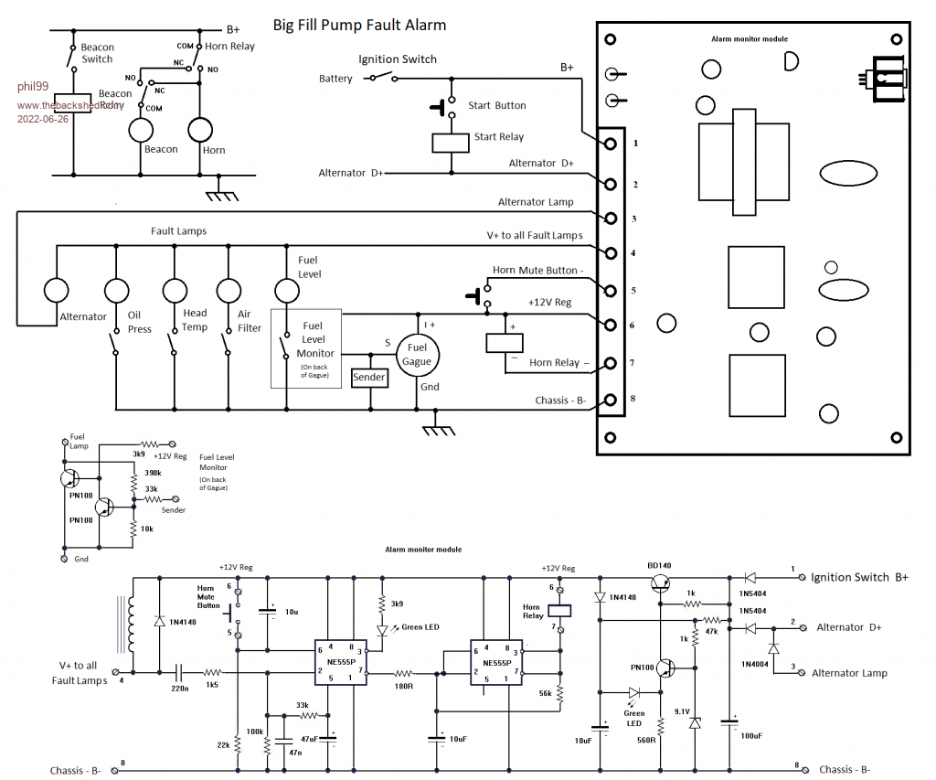 |
||||
| tgerbic Newbie Joined: 25/07/2019 Location: United StatesPosts: 40 |
thwill, You lost me, what were the other end of these 10M and 4.5K resistors attached to? [tony] sorry about that. The resistors were each tried in place of DMM, so hooked between ground and pin 2. The idea was first to check to see if adding a 10M resistive load would cause the circuit to trigger. It did not. I tried some lower values at 10K and 1K to see if either triggered, which did with 1K. So just tried a couple to see how low the resistance needed to be to trigger it. Though the 4.5K would, it make very little sense that this could be the cause, so went looking for another reason. - The book I'm learning electronics from is "Make: Electronics" by Charles Platt [tony] Just curious. There are a lot of books with 555 training in them dating back to the 70s era "Bug Books". Did not recognize that book. - A (nominally) 100nF cap between pins 1 & 2 fixed the problem. [tony] Though it would fix the false triggering (not actually something wrong, as it is behaving as expected considering the characteristics of the DMM), it did not explain why it was happening. Figuring out the actual problem can be an unexpected opportunity to learn something useful. |
||||
| tgerbic Newbie Joined: 25/07/2019 Location: United StatesPosts: 40 |
Turbo46, I looked at a couple of DMMs and see a comp cap near the input. Looked at both of the analog meters I used and they don't have a comp cap on the DC inputs (not needed). Perhaps the take away from this is that having the same path to the measurement circuitry for DC and AC in a meter, like a DMM, affects the DC path. Money saved for the DMM manufacturer but adds a bit of puzzling behavior for the DMM user. tony |
||||
| phil99 Guru Joined: 11/02/2018 Location: AustraliaPosts: 1783 |
Tested a couple of meters on a cheap component tester. Fluke 177 shows up as a 52pF cap. Vichy VC99 shows up as a 9974k resistor - call it 10M. |
||||
| Turbo46 Guru Joined: 24/12/2017 Location: AustraliaPosts: 1593 |
FWIW the next edition of that book does not include the test that started this post and the circuit diagram matches the breadboard. Bill Keep safe. Live long and prosper. |
||||
| thwill Guru Joined: 16/09/2019 Location: United KingdomPosts: 3841 |
Don't tell me you bought a copy Bill ... presumably an eBook unless Amazon delivery times are even more miraculous in Oz. Perhaps I'll have more follow-up on this topic tomorrow, but it's not today's focus. Best wishes, Tom Game*Mite, CMM2 Welcome Tape, Creaky old text adventures |
||||
| Turbo46 Guru Joined: 24/12/2017 Location: AustraliaPosts: 1593 |
No Tom, I found a copy that I could have a look at. Bill Keep safe. Live long and prosper. |
||||
| thwill Guru Joined: 16/09/2019 Location: United KingdomPosts: 3841 |
Thanks again everyone, I know a little more now, one day I may even know enough to be dangerous  . .Incidentally my cheap Chinese component tester reads both my DMMs as 10M? resistors. Best wishes, Tom Game*Mite, CMM2 Welcome Tape, Creaky old text adventures |
||||
| thwill Guru Joined: 16/09/2019 Location: United KingdomPosts: 3841 |
Deleted - TBS reported an error (presumably with the ohm symbol) but then posted it anyway Edited 2022-06-28 21:40 by thwill Game*Mite, CMM2 Welcome Tape, Creaky old text adventures |
||||
| thwill Guru Joined: 16/09/2019 Location: United KingdomPosts: 3841 |
Ditto Edited 2022-06-28 21:40 by thwill Game*Mite, CMM2 Welcome Tape, Creaky old text adventures |
||||
| thwill Guru Joined: 16/09/2019 Location: United KingdomPosts: 3841 |
Ditto - at least it makes my posting stats look good .Edited 2022-06-28 21:41 by thwill Game*Mite, CMM2 Welcome Tape, Creaky old text adventures |
||||
