
|
|
Forum Index : Microcontroller and PC projects : PicoMite VGA
| Author | Message | ||||
| Mixtel90 Guru Joined: 05/10/2019 Location: United KingdomPosts: 5714 |
Ah - it may have internal forward-biased diodes to VCC and you are seeing leakage. You'd be better using a simple BS170, 2N7000 or similar MOSFET on each output, driving the gate directly from the pin, then switching them on & off. You'll get a good open drain output then, at the expense of a bit of board space. Mick Zilog Inside! nascom.info for Nascom & Gemini Preliminary MMBasic docs & my PCB designs |
||||
| JohnS Guru Joined: 18/11/2011 Location: United KingdomPosts: 3654 |
Should R4 be connected to the input (like the other resistors)? John |
||||
| phil99 Guru Joined: 11/02/2018 Location: AustraliaPosts: 1781 |
Try another pin, perhaps that one has become faulty during testing. Here is what I get. > setpin 20,dout � � <---2.4mV > pin(20)=1 � � � � �<---3.3v > setpin 20,din � � �<---315mV of random noise. > Edit. Are you certain the diode is cathode to +? Edited 2022-09-28 18:09 by phil99 |
||||
OA47 Guru Joined: 11/04/2012 Location: AustraliaPosts: 899 |
Sorry John I had left off the junction spot. OA47 |
||||
| OA47 Guru Joined: 11/04/2012 Location: AustraliaPosts: 899 |
Was using pins 5,6 & 7 for the switching so tested with pin 20 (not used previously) SetPin 20 dout.........0V Pin(20)=1 .............3V3 Pin(20)=0 .............0V SetPin 20 din .........0.5V All measured to Analog GND No circuitry attached to Pin 20 Similar results to Phil99 I am using a schottky diode and the anode is definitely to 3V3. OA47 |
||||
| Mixtel90 Guru Joined: 05/10/2019 Location: United KingdomPosts: 5714 |
A DIN pin should be high impedance unless you've used the PULLUP or PULLDOWN option when using SETPIN. Anything else would point to external miswiring (or a damaged pin). Mick Zilog Inside! nascom.info for Nascom & Gemini Preliminary MMBasic docs & my PCB designs |
||||
| OA47 Guru Joined: 11/04/2012 Location: AustraliaPosts: 899 |
Humble pie for supper  The protection diode is no longer a protection diode but more of a resistor. Will chase round the workshop and see if I can find another. OA47 |
||||
| Volhout Guru Joined: 05/03/2018 Location: NetherlandsPosts: 3510 |
Don't forget: all DOUT pins must be DIN before you can measure how high impedance one single pin is.... PicomiteVGA PETSCII ROBOTS |
||||
| Mixtel90 Guru Joined: 05/10/2019 Location: United KingdomPosts: 5714 |
Perhaps you need something a bit meatier than a OA47. ;) Mick Zilog Inside! nascom.info for Nascom & Gemini Preliminary MMBasic docs & my PCB designs |
||||
| OA47 Guru Joined: 11/04/2012 Location: AustraliaPosts: 899 |
Point taken. The original diode was a glass encapsulation. OA47 |
||||
| Mixtel90 Guru Joined: 05/10/2019 Location: United KingdomPosts: 5714 |
Don't let that fool you nowadays. The 1N4148 / 1N914 is a brilliant diode, hence its popularity. :) I do like the old glass diodes though, having got through a few in my time. :) Mick Zilog Inside! nascom.info for Nascom & Gemini Preliminary MMBasic docs & my PCB designs |
||||
| phil99 Guru Joined: 11/02/2018 Location: AustraliaPosts: 1781 |
Volhout said: " For this diode to work, it should be a shottky diode. And these tend to have high leakage (1uA). " Could that leakage be the problem? Temporarily remove it, leave the input open circuit then measure the voltage on the pin in all conditions. If that is it then some other protection measure will be needed. Edit Ignore that I missed the post where you found the problem. Edited 2022-09-28 21:57 by phil99 |
||||
| phil99 Guru Joined: 11/02/2018 Location: AustraliaPosts: 1781 |
Assuming this input attenuator is for a scope, frequency compensation will be needed to get the best out of it. Since the Pico input has capacitance you need a capacitive divider that matches the resistive one. 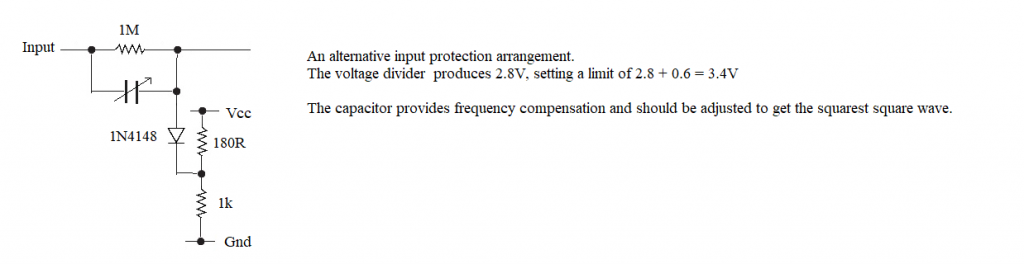 |
||||
| JohnS Guru Joined: 18/11/2011 Location: United KingdomPosts: 3654 |
Roughly what value capacitor? John |
||||
TassyJim Guru Joined: 07/08/2011 Location: AustraliaPosts: 5898 |
To answer that, you have to know the input capacitance of the device the probe is connected to. Jim VK7JH MMedit MMBasic Help |
||||
| Volhout Guru Joined: 05/03/2018 Location: NetherlandsPosts: 3510 |
I am not sure OA47 is going to build an oscilloscope, so the capacitor may not be needed. About the capacitor: If you want to measure 50/60Hz or DC it is not needed. The capacitor is needed to balance against the input capacitance of the pico ADC, and the impedance of the circuit board. The balance (ratio) should be identical to the ratio of the resistor divider. Since the resistor divider is switching, you will have to switch the capacitance also. What they do in oscilloscopes is that they add capacitors everwhere. Practical values in your case would be (look at the schematics OA47 provides). If C1 = 15pF, and the input capacitance of the pico and board layout is 7pF (estimate) Capacitor parallel to R1 is 22pF (1M R1/1M R2 attenuator) Capacitor parallel to R3 is 200pF (2x100pF) (1M R1/100k R3 attenuator) Capacitor parallel to R4 is 2200pF (1M R1/10k R4 attenuator) But again, for DC and 50Hz this is not needed. PicomiteVGA PETSCII ROBOTS |
||||
| OA47 Guru Joined: 11/04/2012 Location: AustraliaPosts: 899 |
Here is a screen shot of the project. Not a desktop DVM but a shelftop DVM, one I can monitor from many meters away. 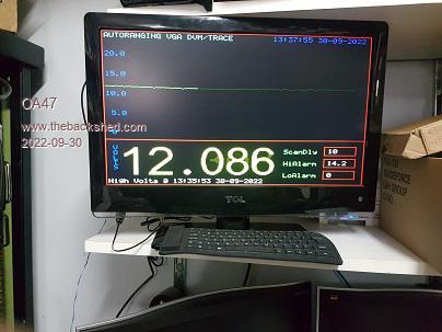 OA47 Edited 2022-09-30 15:35 by OA47 |
||||
| Volhout Guru Joined: 05/03/2018 Location: NetherlandsPosts: 3510 |
Nice project! A monitoring system. And yes, readable from a distance... PicomiteVGA PETSCII ROBOTS |
||||
| OA47 Guru Joined: 11/04/2012 Location: AustraliaPosts: 899 |
The use of an old LCD TV makes things easy as it can supply the pico from USB, has VGA input and audio input all readily accessible and the system can be powered down via IR remote. Here is a pic of the prototype pcb so far. 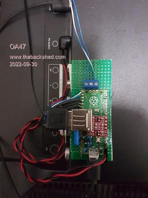 |
||||
