
|
|
Forum Index : Microcontroller and PC projects : Frequency counter using PIO, work in progress for picomite
| Page 1 of 2 |
|||||
| Author | Message | ||||
| Volhout Guru Joined: 05/03/2018 Location: NetherlandsPosts: 3552 |
Below is a small program that uses the PIO (PIO1 to make it work with VGA picomite) to measure a frequency. The method used is: You write a gate time to PIO 1.0 FIFO PIO 1.0 outputs a gate pulse (active low) of so many microseconds on GP0. You can see a LED blink when attached to GP0). PIO 1.1 clocked at 63MHz, samples this gate pulse, and uses it to start/stop counting pulses on GP1 (input pin). After the gate time has finished, in MMBasic you can read the frequency value from the PIO 1.1 FIFO register. The program is not yet finished, but with 63MHz clock on PIO 1.1 it already measures frequencies over 6 MHz. Please use the code, and improve where needed. At the moment I see a few percent error above 4 MHz, and will work on it to find out, but it is accurate up to 2 MHz. The coded uses PWM on PWM1 as a test signal (pin GP2), that must be wired to GP1 to give a reading. But that is only for testing. Watch out: PWM (Peter mentioned this before) has a finite number of settings, and will not be accurate at high frequencies. The counter should be more accurate than PWM.... 'architecture 'PIO machine 1.0 generates a progr. gate signal on GP0 (side set pin GP0) 'PIO machine 1.1 uses the gate signal to count GP1 pulses 'PIO 1.0 (gate) 'adress data comment '0 91A0 pull block .side(1) 'pull data from FIFO into OSR when available '1 B027 mov(x,osr) .side(1) 'load gate time (in clock pulses) from osr '2 0042 jmp(x_dec, this line) .side(0) '1 cycle count down + gate low '3 1000 jmp 00 .side(1) � 'loop back 'PIO 1.1 (count) '4 A02B mov(x,-1) 'x = -1 '5 2080 wait(1,pin,0) 'sync '6 2000 wait(0,pin,0) 'detect falling edge of gate '7 2001 wait(0,pin,1) 'wait for risig edge pulse '8 2081 wait(1,pin,1) 'wait for falling edge pulse '9 00CB jmp(pin, pc=0x0b) 'still counting ? 'A 0047 jmp(x_dec, pc=0x07) 'yes, count next pulse 'B A0C9 mov(isr,-x) 'copy counter to isr 'C 8000 push noblock 'get value to FIFO 'D 0004 jmp 04 'prepare for next gate pulse 'this is above program in data statements dim a%(7)=(&h10000042B02790A0,&h200120002080A02B,&hA0C9004700CB2081,&h48000,0,0,0,0) 'SETUP code setpin gp0,pio1 � � � � �'side output setpin gp1,pio1 � � � � �'input 'program above code in the chip in PIO 1 pio program 1,a%() 'PIO 1.0 f0=1e6 � � � � � � � � � �'1 MHz frequency gate resolution e0=pio(execctrl 0,0,&h1f) � � � � 'default value p0=Pio(pinctrl 1,1,,,gp0,gp0,) � �'GP0 side set, GP0 SET (for pindirs) pio init machine 1,0,f0,p0,e0,0,0 'start from 0x00 'PIO 1.1 f1=63e6 � � � � � � � � � � �'63 MHz frequency e1=pio(execctrl 0,4,&h1f) � � � � 'default value for this machine p1=Pio(pinctrl 0,0,0,gp0,,,) � � �'GP0 base for inputs pio init machine 1,1,f1,0,e1,0,4 �'start from 0x04 pio execute 1,0,&hE081 � � � � � �'set GP0 output PIO start 1,0 'this will wait for data to arrive in FIFO, then generate 1 gate PIO start 1,1 'this will start counter, waiting on adress 7 for GP0 to become low 'MAIN CODE 'generate a test frequency setpin gp2,pwm pwm 1,1000000,50 'this is the counter code dim r%(3) gate_time = 0.1 � � � � � � � � � �'seconds gate_clocks% = gate_time*1e6 � � � 'for 1MHz PIO gate clock do 'put gate time in PIO 1.0 OSR (gate time is specified in PIO cycles, could be 1MHz, 10MHz..) �pio read 1,1,4,r%() � � � � � � � 'empty fifo pio write 1,0,1,gate_clocks% � �'this starts the gate pulse generator, single pulse 'wait gate time + few us pause 200 'get FIFO value pio read 1,1,4,r%() 'print FIFO/gate time value print r%(1)/gate_time loop In theory this should work up to 20MHz when using a 126MHz PIO clock (ARM running at 252MHz). Edited 2022-12-09 04:19 by Volhout PicomiteVGA PETSCII ROBOTS |
||||
| twofingers Guru Joined: 02/06/2014 Location: GermanyPosts: 1133 |
@Volhout Thanks! I like your PIO code examples!  Best regards Michael |
||||
| Pluto Guru Joined: 09/06/2017 Location: FinlandPosts: 330 |
Thanks Volhout! Excited to see how high you can go (in frequency). Fred |
||||
| Tinine Guru Joined: 30/03/2016 Location: United KingdomPosts: 1646 |
The RP2040 doesn't have built-in counters that can get to, say, sysclock/2? Kinda lame, for a modern MCU if it can't count. Craig |
||||
| Tinine Guru Joined: 30/03/2016 Location: United KingdomPosts: 1646 |
For contrast: A 2006 MCU (running @80MHz) programmed in 100% PropBasic: 40MHz Reciprocal Frequency Counter in PropBasic Now, the P2? All 64 smartpins can count sysclock/2 without any assistance from the 8 CPUs. Craig |
||||
| Volhout Guru Joined: 05/03/2018 Location: NetherlandsPosts: 3552 |
Tinine, I am sure the rp2040 has hardware that can do it. MMBasic does not use this hardware and uses software for the frequency counting. The pio program above is a method to measure higher frequencies in the MMBasic domain. And it is educating me how to use the pio. Pluto, The pio code you where using previosly determines frequency by measuring the period of the signal, and converting to frequency. Accurate at lower frequency, but not at high frequencies. The LC meter triggered me to work on a solution This pio code is more accurate since it measures the number of cycles. Volhout Edited 2022-12-09 16:26 by Volhout PicomiteVGA PETSCII ROBOTS |
||||
| Tinine Guru Joined: 30/03/2016 Location: United KingdomPosts: 1646 |
Gotcha  |
||||
| matherp Guru Joined: 11/12/2012 Location: United KingdomPosts: 8592 |
Actually I think Craig is right on this one. All normal ST ARM chips have timers that can be externally clocked and will count up to the processor speed /2 I am unable to find if it is possible on the RP2040. There are two pins GP20 and GP22 which can accept a clock input (Alternate function F8) but there don't seem to be any general purpose timers that these can be allocated to. I think the assumption is that PIO should be used for this sort of thing. It is in my view a significant weakness of the RP2040. |
||||
| Mixtel90 Guru Joined: 05/10/2019 Location: United KingdomPosts: 5735 |
The RP2040 appears to have a specialised frequency counter (see p211 - 2.15.4 & 215 - 2.5.6.2 of the RP2040 Data Sheet ). It looks like you can set FC0_SRC to gpin0 or gpin1 for gpio pin inputs. It counts clock pulses and returns a done signal in FC0_STATUS. Mick Zilog Inside! nascom.info for Nascom & Gemini Preliminary MMBasic docs & my PCB designs |
||||
| Volhout Guru Joined: 05/03/2018 Location: NetherlandsPosts: 3552 |
Tested the frequency counter and debugged it. This version is working fine, and shows very accurate frequency readings up to 15.75MHz (PIO 1.1 running at 63MHz). For my application that is enough. 'Frequency counter using RP2040 PIO 'PIO machine 1.0 generates a progr. gate signal on GP0 (side set pin GP0) 'PIO machine 1.1 uses the gate signal to count GP1 pulses 'PIO program and configuration ------------------------------------------------------ 'PIO 1.0 (gate) 'adress data � mnemonics � � � � � � � � � � � � comment ' �0 � �E081 � set pindir 00001 � � � � � � � � �'set GP0 to output ' �1 � �91A0 � pull block .side(1) � � � � � � � 'pull data from FIFO into OSR when available ' �2 � �B027 � mov(x,osr) .side(1) � � � � � � � 'load gate time (in clock pulses) from osr ' �3 � �0043 � jmp(x_dec, this line) .side(0) � �'1 cycle count down + gate low ' �4 � �1001 � jmp 01 .side(1) � � � � � � � � � 'loop back 'PIO 1.1 (count) ' �5 � �A02B � mov(x,-1) � � � � � � � � � � � � 'x = -1 ' �6 � �2080 � wait(1,pin,0) � � � � � � � � � � 'sync ' �7 � �2000 � wait(0,pin,0) � � � � � � � � � � 'detect falling edge of gate ' �8 � �2001 � wait(0,pin,1) � � � � � � � � � � 'wait for risig edge pulse ' �9 � �2081 � wait(1,pin,1) � � � � � � � � � � 'wait for falling edge pulse ' �A � �00CC � jmp(pin, pc=0x0c) � � � � � � � � 'continue counting ? ' �B � �0048 � jmp(x_dec, pc=0x08) � � � � � � � 'yes, count next pulse ' �C � �A0C9 � mov(isr,-x) � � � � � � � � � � � 'copy counter to isr ' �D � �8000 � push noblock � � � � � � � � � � �'get value to FIFO ' �E � �0005 � jmp 05 � � � � � � � � � � � � � �'prepare for next gate pulse 'this is above program in data statements dim a%(7)=(&h0043B02791A0E081,&h20002080A02B1001,&h004800CC20812001,&h58000A0C9,0,0,0,0) 'SETUP code setpin gp0,pio1 � � � � �'side output setpin gp1,pio1 � � � � �'input 'program above code in the chip in PIO 1 pio program 1,a%() 'PIO configuration ------------------------------------------------------------------------- 'PIO 1.0 f0=1e6 � � � � � � � � � � � � � �'1 MHz frequency gate resolution e0=pio(execctrl 0,0,&h1f) � � � � 'default value p0=Pio(pinctrl 1,1,,,gp0,gp0,) � �'GP0 side set, GP0 SET (for pindirs) pio init machine 1,0,f0,p0,e0,0,0 'start from 0x00 'PIO 1.1 f1=63e6 � � � � � � � � � � � � � '63 MHz frequency e1=pio(execctrl 0,5,&h1f) � � � � 'default value for this machine p1=Pio(pinctrl 0,0,0,gp0,,,) � � �'GP0 base for inputs pio init machine 1,1,f1,0,e1,0,5 �'start from 0x05 'Start both PIO sequencers PIO start 1,0 'this will wait for data to arrive in FIFO, then generate 1 gate PIO start 1,1 'this will start counter, waiting on adress 7 for GP0 to become low 'MMBASIC MAIN CODE -------------------------------------------------------------------------- 'generate a test frequency on GP2, for testing of the counter setpin gp2,pwm pwm 1,15000000,50 � � � � � � � � � ' change 15000000 to test different frequencies. � � � � � � � � � � � � � � � � � �'15MHz PLL generates 15.75MHz dues to divider settings inside the PLL 'variables and constants used in the counter dim r%(3),c% � � � � � � � � � � � �'define variables, r%() only used to empty fifo gate_time = 0.1 � � � � � � � � � � 'seconds gate_clocks% = gate_time*1e6 - 1 � �'for 1MHz PIO gate clock as integer (n counts (n-1...0)) 'this loop does the actual counting do �'put gate time in PIO 1.0 OSR (gate time is specified in PIO cycles, could be 1MHz, 10MHz..) �pio read 1,1,4,r%() � � � � � � � 'empty fifo from rubbish (only needed at start) �pio write 1,0,1,gate_clocks% � � �'this starts the gate pulse generator, single pulse �'wait gate time + few ms for printing data �pause (1000*gate_time + 200) �'get FIFO value �pio read 1,1,1,c% � � � � � � � � 'read value from FIFO (there is only 1 value in it) �c%=c%/gate_time � � � � � � � � � 'convert or Hz �'print frequency value �print "GP1 frequency = ";c%;" Hz" loop For those who want to try higher frequencies, you can increase the f1 value (frequency running PIO 1.1). Do not touch the f0 version (PIO 1.0) since you risk loosing accuracy. Enjoy.... I will use this for the LC meter that Pluto prototyped, to increase accuracy. Volhout P.S. in case there is interest, I would be happy to share the knowledge that I acquired during my hours and hours of studying the PIO and it's capabilities in some sort of written form. Maybe a growing thread on the forum. But just in case there is interest in it. There are quite some differences between the way the RP2040 python world works and the MMBasic way of doing things, so google will most likely confuse you more. Most of the complexity around PIO is in the correct relation between the PIO program and the PIO configuration. Edited 2022-12-09 21:08 by Volhout PicomiteVGA PETSCII ROBOTS |
||||
| Pluto Guru Joined: 09/06/2017 Location: FinlandPosts: 330 |
Congratulations! Just started testing and it works very well. My first observations: -Using the PWM as input (15MHz). The measured frequency is 15.12MHz measured by your new program and the same result with a purchased low resolution 5-digits meter. In the program listing you say it should be 15.75MHz. -When using DDS Signal Generator by Geoff https://geoffg.net/SignalGenerator.html, I get at frequencies above 400kHz readings that are 10 Hz high. It is fluctuating between 400000 and 400010. At 3MHz it is 30Hz high. Not a problem at all for me; just wanted to report to you. -When disconnecting the signal source from the running meter, it continues to show the last measurement. Could be a source for confusion when used in an application. Any possibility to get it to allways show 0Hz without input signal? Re: PIO-programming knowhow. Yes I would be interested to try to learn...but the chances to pass the exam might however be limited. I am sure there are many others who would be interested in a Picomite PIO-programming Bible. Thanks! Fred |
||||
| Volhout Guru Joined: 05/03/2018 Location: NetherlandsPosts: 3552 |
Hi PLuto, #1: the actual frequency from the PWM depends on it's clock. In my case the CPU runs at 252MHz. You may be running a different clock. With 252MHz, the 15MHz command send to the PWM translates to 15.75MHz, which is exactly 63MHz divided by 4. Important is that what your external frequency counter says is identical to what the picomite says... #2: need to think on that one. When there is absolute no input clock in the gate timeframe, the PIO code waits forever, and never pushes a value into the FIFO (instruction at address 8 or 9). So the FIFO keeps showing the last valid value. It may need an extra logic signal... #3: that is why I ask. Don't want to spend a lot of time when no-one even reads it. About the DDS generator: the gate time in my code is 0.1second. That measn that fluctuations between 400000 and 400010 are actually only 1 count. Change gate_time to 1, and you will get more accurate results. Edited 2022-12-09 23:48 by Volhout PicomiteVGA PETSCII ROBOTS |
||||
| Pluto Guru Joined: 09/06/2017 Location: FinlandPosts: 330 |
Hi Volhout. I found an easy way to get 0Hz reading when signal input is removed. I just provide the input GP1 with a low frequency signal. Just put a 100k resistor from GP1 to GP0, which your program already a low freq output on. This resistor can be permanently connected. It does not seem to disturb the measurement when you have a signal source connected. If you do not wish to have the resistor and you have cables connected to the GP1 when you remove the signal source, the cable will pick up 50Hz from the surroundings and output 50Hz. This value is of course not zero, but it will be an indication of a missing signal source. |
||||
| Volhout Guru Joined: 05/03/2018 Location: NetherlandsPosts: 3552 |
Hi Pluto, Please find attached code that shows "no input signal". When the PIO 1.1 is stuck waiting for signal, it leaves pin GP2 high. The basic program checks for this, and shows text. Note that GP3 is the PWM signal to provide the test frequency (not GP2). This fix is possible due to Peters fix, that allows to read a POI assigned pin (setpin xx,pio) in the basic program, even when it is not assigned an input. Thanks Peter !! I run this on CPUSPEED 252000, software 5.07.05RC8 'Frequency counter using RP2040 PIO 'PIO machine 1.0 generates a progr. gate signal on GP0 (side set pin GP0) 'PIO machine 1.1 uses the gate signal to count GP1 pulses 'PIO program and configuration ------------------------------------------------------ 'PIO 1.0 (gate) 'adress data � mnemonics � � � � � � � � � � � � comment ' �0 � �E081 � set pindir 00001 � � � � � � � � �'set GP0 to output ' �1 � �91A0 � pull block .side(1) � � � � � � � 'pull data from FIFO into OSR when available ' �2 � �B027 � mov(x,osr) .side(1) � � � � � � � 'load gate time (in clock pulses) from osr ' �3 � �0043 � jmp(x_dec, this line) .side(0) � �'1 cycle count down + gate low ' �4 � �1001 � jmp 01 .side(1) � � � � � � � � � 'loop back 'PIO 1.1 (count) ' �5 � �A02B � mov(x,-1) .side(0) � � � � � � � �'x = -1 ' �6 � �2080 � wait(1,pin,0) .side(0) � � � � � �'sync ' �7 � �2000 � wait(0,pin,0) .side(0) � � � � � �'detect falling edge of gate ' �8 � �3001 � wait(0,pin,1) .side(1) � � � � � �'wait for risig edge pulse ' �9 � �3081 � wait(1,pin,1) .side(1) � � � � � �'wait for falling edge pulse ' �A � �00CC � jmp(pin, pc=0x0c) .side(0) � � � �'continue counting ? ' �B � �0048 � jmp(x_dec, pc=0x08) .side(0) � � �'yes, count next pulse ' �C � �A0C9 � mov(isr,-x) .side(0) � � � � � � �'copy counter to isr ' �D � �8000 � push noblock .side(0) � � � � � � 'get value to FIFO ' �E � �0005 � jmp 05 .side(0) � � � � � � � � � 'prepare for next gate pulse 'this is above program in data statements dim a%(7)=(&h0043B02791A0E081,&h20002080A02B1001,&h004800CC30813001,&h58000A0C9,0,0,0,0) 'SETUP code setpin gp0,pio1 � � � � �'gate signal setpin gp1,pio1 � � � � �'frequency counter input setpin gp2,pio1 � � � � �'no signal output used to display input signal missing 'program above code in the chip in PIO 1 pio program 1,a%() 'PIO configuration ------------------------------------------------------------------------- 'PIO 1.0 f0=1e6 � � � � � � � � � � � � � �'1 MHz frequency gate resolution e0=pio(execctrl 0,0,&h1f) � � � � 'default value p0=Pio(pinctrl 1,1,,,gp0,gp0,) � �'GP0 side set, GP0 SET (for pindirs) pio init machine 1,0,f0,p0,e0,0,0 'start from 0x00 'PIO 1.1 f1=63e6 � � � � � � � � � � � � � '63 MHz frequency e1=pio(execctrl 0,5,&h1f) � � � � 'default value for this machine p1=Pio(pinctrl 1,1,,gp0,gp2,gp2,) 'GP0 base for inputs, GP2 out for status pio init machine 1,1,f1,p1,e1,0,5 'start from 0x05 'Start both PIO sequencers pio execute 1,1,&hE081 � � � � � �'set GP2 output PIO start 1,0 'this will wait for data to arrive in FIFO, then generate 1 gate PIO start 1,1 'this will start counter, waiting on adress 7 for GP0 to become low 'MMBASIC MAIN CODE -------------------------------------------------------------------------- 'generate a test frequency on GP3, for testing of the counter setpin gp3,pwm pwm 1,15000000,,50 � � � � � � � � 'change 15000000 to test different frequencies. � � � � � � � � � � � � � � � � � '15MHz PLL generates 15.75MHz dues to divider settings inside the PLL 'variables and constants used in the counter dim r%(3),c% � � � � � � � � � � � �'define variables, r%() only used to empty fifo gate_time = 0.1 � � � � � � � � � � 'seconds gate_clocks% = gate_time*f0 - 1 � � 'for 1MHz PIO gate clock as integer (n counts (n-1...0)) 'this loop does the actual counting do �if pin(gp2)=1 then � � �print "no input signal" � �pause 200 � �else � � �'put gate time in PIO 1.0 OSR (gate time is specified in PIO cycles, could be 1MHz, 10MHz..) � �pio read 1,1,4,r%() � � � � � � � 'empty fifo from rubbish (only needed at start) � �pio write 1,0,1,gate_clocks% � � �'this starts the gate pulse generator, single pulse � �'wait gate time + few ms for printing data � �pause (1000*gate_time + 200) � �'get FIFO value � �pio read 1,1,1,c% � � � � � � � � 'read value from FIFO (there is only 1 value in it) � �c%=c%/gate_time � � � � � � � � � 'convert or Hz � �'print frequency value � �print "GP1 frequency = ";c%;" Hz" �end if loop P.S. just tested f1=126e6 (126 MHz PIO speed). The counter works fine up to 31MHz. Volhout Edited 2022-12-10 05:37 by Volhout PicomiteVGA PETSCII ROBOTS |
||||
| circuit Senior Member Joined: 10/01/2016 Location: United KingdomPosts: 231 |
@Volhout, +1 for ANY educational material on PIO. I read all your posts with great interest though not always with full understanding; always appreciative of more information and education. You would certainly NOT be wasting your time! |
||||
| phil99 Guru Joined: 11/02/2018 Location: AustraliaPosts: 1790 |
+2 Echo Circuit's post. Though my ability to use it may be limited (old dogs...new tricks etc.) your explanations are clear and interesting. |
||||
| JohnS Guru Joined: 18/11/2011 Location: United KingdomPosts: 3661 |
I'm interested, too, please. John |
||||
| panky Guru Joined: 02/10/2012 Location: AustraliaPosts: 1094 |
+3 echo Circuit's post - I also find very interesting. Would be happy to assist with any formal documentation. Regards, Doug. ... almost all of the Maximites, the MicromMites, the MM Extremes, the ArmMites, the PicoMite and loving it! |
||||
| Volhout Guru Joined: 05/03/2018 Location: NetherlandsPosts: 3552 |
I will see what I can do. Expect a new growing thread about pio. Maybe 1 chapter/post every few days, so people have time to grow knowlegde in stad of being overwhelmed. Maybe combine it with some form of excercise.. Volhout Edited 2022-12-10 18:59 by Volhout PicomiteVGA PETSCII ROBOTS |
||||
| Pluto Guru Joined: 09/06/2017 Location: FinlandPosts: 330 |
Volhout, some more testing of your latest PIO code ...... @CPU378MHz, f1=378e6, pwm 1,90000000,,50: --> 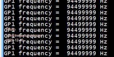 94.5MHz "confirmed" by FM-radio. 10cm wire on the GP3 makes an FM transmitter with receivable signal >10m indoors. An other frequency meter (cheap) also shows 94.5015MHz. |
||||
| Page 1 of 2 |
|||||
