
|
|
Forum Index : Microcontroller and PC projects : Picomite to Picomite via I2C
| Page 1 of 2 |
|||||
| Author | Message | ||||
| circuit Senior Member Joined: 10/01/2016 Location: United KingdomPosts: 231 |
In his most excellent book, "Getting Started with the Micromite", Geoff describes on Pages 70 through 73 a control program to convert a Micromite into a general purpose I/O expansion chip using I2C. I have been trying to translate this for Picomite to Picomite with much frustration. It took me some time to realise that one reason the thing was falling over is because the dialect of MMBasic for Micromite is different to that for the Picomite in one important aspect. Micromite Basic allows configuration of I/O pins by setting a configuration number of 0 to 9; this does not appear to have been translated through to the Picomite. (It would be nice to have this back, anyway). Before I start banging my head against a wall trying to reconfigure the original programs, I thought to ask here for help from those who are more expert. Perhaps Geoff may even have already done this for a new edition of the book and might make it available. Anyhow, I would be most appreciative of any guidance as to how this program should be written for the Picomite. |
||||
| Amnesie Guru Joined: 30/06/2020 Location: GermanyPosts: 382 |
Good point, I would be also interested in this :) Greetings Daniel |
||||
| stanleyella Guru Joined: 25/06/2022 Location: United KingdomPosts: 1647 |
page 142 to 144 in picomite manual seems to show how to i2c connect 2 picomites |
||||
| lizby Guru Joined: 17/05/2016 Location: United StatesPosts: 3016 |
You might find serial more convenient. 3 different methods explored here The main examples are MMB4W to picomite, but picomite to picomite was also tested, and picomite to micromite should also work. PicoMite, Armmite F4, SensorKits, MMBasic Hardware, Games, etc. on fruitoftheshed |
||||
| stanleyella Guru Joined: 25/06/2022 Location: United KingdomPosts: 1647 |
I used mcp23017 16 pin i2c expander with picomite, help from andy on the forum and it got slated for slow but I think nice. post code if wanted |
||||
| circuit Senior Member Joined: 10/01/2016 Location: United KingdomPosts: 231 |
Lost you on that one, I am afraid; Pages 142 to 144 in the Picomite Manual are in the middle of the FUNCTIONS listings. Which manual are you using? |
||||
| circuit Senior Member Joined: 10/01/2016 Location: United KingdomPosts: 231 |
Well, I would like to stick with Picomite to Picomite because it gives me remote to 30 pins in one unit, but I would still like to see your I2C code for the MCP33017 and would appreciate you posting it. |
||||
| stanleyella Guru Joined: 25/06/2022 Location: United KingdomPosts: 1647 |
hi circuit, here's a test prog to read 8 buttons.vga display ' mode 1 option autorun on OPTION EXPLICIT OPTION DEFAULT NONE dim integer porta_bits,portb_bits const mcp23017 = &h20 ' A2, A1, A0, R/W all connected to 0V Const i2caddr=mcp23017 const IODIRA = &h00 ' Port A IO Direction register DEFAULT = I/P const IODIRB = &h01 ' Port B IO Direction register DEFAULT = I/P const IOCON = &h0A ' IO Expander config register - address &h0B accesses same register const GPIOA = &h12 ' Port A General purpose register const GPIOB = &h13 ' Port B General Purpose register const OLATA = &h14 ' Port A latch register const OLATB = &h15 ' Port B latch register const GPUPA = &h0C ' Port C pull-up register const GPUPB = &h0D ' Port B pull-up register ' I2C WRITE MCP23017,0,2,IODIRA,255 ' set direction to input I2C WRITE MCP23017,0,2,IODIRB,255 ' set direction to input I2C WRITE MCP23017,0,2,GPUPB,&hff ' set weak pullups on all ' Font 5 CLS ' Do get_portb_bits text 0,20,bin$(portb_bits,8) text 0,60,str$(portb_bits) Pause 100 Loop sub get_portb_bits I2C WRITE MCP23017,0,1,GPIOB ' set the register to read I2C READ MCP23017,0,1,portb_bits ' read the B port end sub 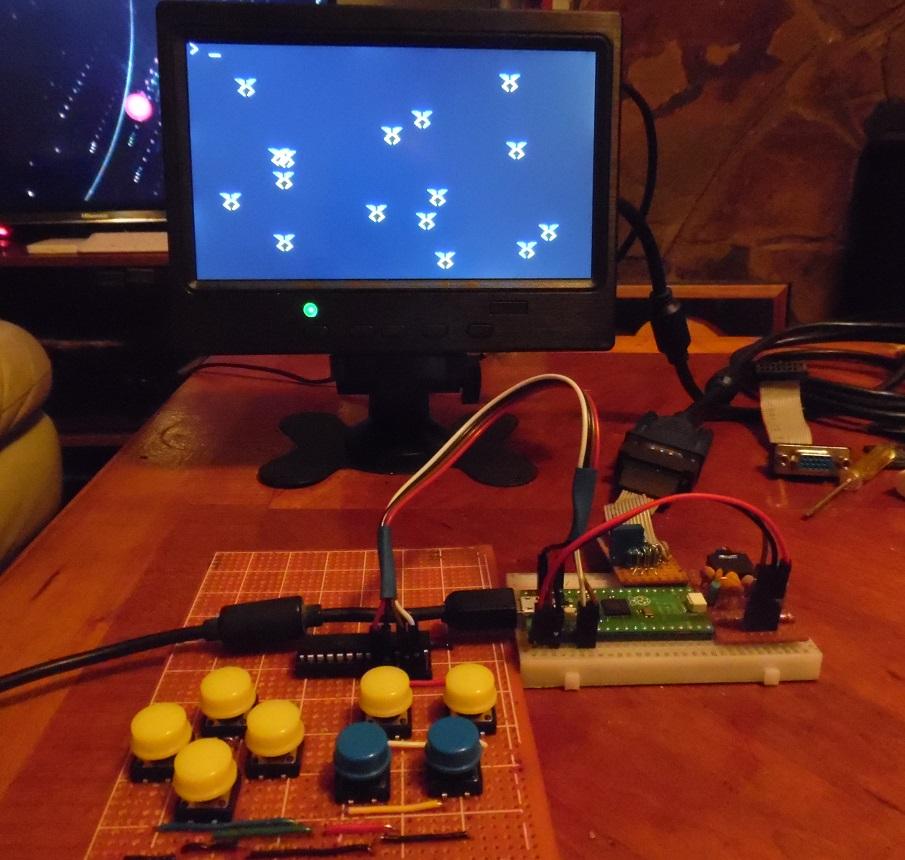 |
||||
TassyJim Guru Joined: 07/08/2011 Location: AustraliaPosts: 5911 |
Try Appendix B – I2C Communications With I2C you have to stay in sync. With serial, you have the Tx and Rx buffers that give you a bit of slack which might make programming easier. Jim VK7JH MMedit MMBasic Help |
||||
| stanleyella Guru Joined: 25/06/2022 Location: United KingdomPosts: 1647 |
Jim, I had vlox i2c rangefinder and ssdi306 i2c to display range and i2c 16 port expander all working same time from same 2 pins User Manual MMBasic Ver 5.07.06 This is an example of communications between two PicoMites where one is the master and the other is the slave. First the master: SETPIN GP2, GP3, I2C2 I2C2 OPEN 100, 1000 i = 10 DO i = i + 1 a$ = STR$(i) I2C2 WRITE &H50, 0, LEN(a$), a$ PAUSE 200 I2C2 READ &H50, 0, 8, a$ PRINT a$ PAUSE 200 LOOP Then the slave: SETPIN GP2, GP3, I2C2 I2C2 SLAVE OPEN &H50, tint, rint DO : LOOP SUB rint LOCAL count, a$ I2C2 SLAVE READ 10, a$, count PRINT LEFT$(a$, count) END SUB SUB tint LOCAL a$ = Time$ I2C2 SLAVE WRITE LEN(a$), a$ END SUB Page 144 |
||||
| robert.rozee Guru Joined: 31/12/2012 Location: New ZealandPosts: 2290 |
hi 'circuit', i can remember the support for using a numeric value for the I2C sub-function being dropped a few years back, but can not remember who did it - Peter or Geoff. at the time i believe the rationale was that it was a rarely used feature, and support for it within the interpreter was difficult to maintain. perhaps Peter of Geoff can comment further? you can always use a numeric value in your 'master' pico code, and then have the 'slave' pico do a SELECT ... CASE thing to break it back out into a whole load of separate calls to I2C.... there are less than a dozen sub-functions as i recall. if you wanted blindingly fast communications between two picos, ask Peter to enable CDC support in the USB picomite firmware. this would allow two picos to talk to each other over the USB link at 12Mbps over virtual comm ports - one pico would be running the USB firmware and act as host, while the other would run the regular firmware and act as device. cheers, rob :-) Edited 2024-04-08 12:03 by robert.rozee |
||||
| Volhout Guru Joined: 05/03/2018 Location: NetherlandsPosts: 3552 |
I2C communication master-slave The information is in all PicoMite user manuals in Appendix B "I2C communication". I would also prefer UART communication over I2C communication unless you have multiple clients (slaves). With UART communication you the possibility to increase the distance between 2 devices using RS232 or RS485/RS422 buffer chips without problems. With I2C that is more difficult...to impossible. I like your suggestion Rob, but then you are limitted to the cable length of a USB cable. And PicoMite UARTS can reach significant UART baudrate already, far more than MMBasic can handle. Yes.. you can fill your buffer fast, but do something usefull with the data in MMBasic is the bottleneck at these high speeds. Volhout Edited 2024-04-08 18:04 by Volhout PicomiteVGA PETSCII ROBOTS |
||||
| Geoffg Guru Joined: 06/06/2011 Location: AustraliaPosts: 3165 |
You can easily use the Micromite I2C communications program on the PicoMite by using an IF...THEN...ELSE... structure to convert the configuration number into a command. For example this is the new program running on the slave PicoMite: OPTION AUTORUN ON DIM msg(2) ' array used to hold the message I2C SLAVE OPEN &H26, 0, 0, WriteD, ReadD ' slave's address is 26 (hex) DO ' the program loops forever WATCHDOG 1000 ' this will recover from errors LOOP SUB ReadD ' received a message I2C SLAVE READ 3, msg(), recvd ' get the message into the array IF msg(0) = 1 THEN ' command = 1 IF msg(2) = 0 THEN SETPIN msg(1), OFF ' Not configured ELSEIF msg(2) = 1 THEN SETPIN msg(1), AIN ' Analog input ELSEIF msg(2) = 2 THEN SETPIN msg(1), DIN ' Digital input ELSEIF msg(2) = 3 THEN SETPIN msg(1), FIN ' Frequency input ELSEIF msg(2) = 4 THEN SETPIN msg(1), PIN ' Period input ELSEIF msg(2) = 5 THEN SETPIN msg(1), CIN ' Counting input ELSEIF msg(2) = 8 THEN SETPIN msg(1), DOUT ' Digital output ENDIF ELSEIF msg(0) = 2 THEN ' command = 2 PIN(msg(1)) = msg(2) ' set the I/O pin's output ELSE ' the command must be 3 s$ = str$(pin(msg(1))) + Space$(12) ' get the input on the I/O pin ENDIF END SUB ' return from the interrupt SUB WriteD ' request from the master I2C SLAVE WRITE 12, s$ ' send the last measurement END SUB ' return from the interrupt Note that this does not include open collector outputs (the PicoMite does not support this mode) or the extended functionality provided by option arguments (for example PULLUP or PULLDOWN). Also, this is untested. Although it should work  Geoff Geoff Graham - http://geoffg.net |
||||
| robert.rozee Guru Joined: 31/12/2012 Location: New ZealandPosts: 2290 |
for an I/O expander, personally i would most often want the two picos right next to each other on the same PCB. you are right though, for long distances RS232 or similar would be more suitable - although i have used USB cables that are 5m or more long without major issue, remembering we are only running at 12Mbps for CDC. cheers, rob :-) |
||||
| PhenixRising Guru Joined: 07/11/2023 Location: United KingdomPosts: 304 |
This works a treat @921,600 Baud |
||||
| stanleyella Guru Joined: 25/06/2022 Location: United KingdomPosts: 1647 |
The mcp23017 I've used for 8 buttons input and a robot using 2 geared stepper motors 4 pins each, port set out. using a pico , if you can get type c 4M for £1.49 from ae then maybe valid for i2c expander but seems a waste of mmb for a dedicated trivial purpose imho, a dedicated device worth trying just cos it'll be a chip not a board. short i2c leads and 4.7k pullups every time? stan |
||||
| lizby Guru Joined: 17/05/2016 Location: United StatesPosts: 3016 |
But what exactly is being wasted? And maybe the purposes aren't all that trivial. Maybe at some later date you decide you want your I/O to include PWMing some LEDs. Or gathering more than 4 ADC readings in addition to having more digital I/O. Or reading some DS18B20s. Or counting fairly fast pulses to measure water flow. As far as distance goes, I've succeeded with 3V3 serial over 50 feet of Cat5 (in an undemanding environment). PicoMite, Armmite F4, SensorKits, MMBasic Hardware, Games, etc. on fruitoftheshed |
||||
| circuit Senior Member Joined: 10/01/2016 Location: United KingdomPosts: 231 |
Gosh, so many useful posts; many thanks to all. I shall try and implement Geoff's code, but I am most interested in all the suggestions, some tantalisingly attractive. A long time ago I did have success with an mcp23017 chip for outputs so I might look at this again. The serial suggestions also seem a very logical approach and I will look at this further. What I am looking for is the simplest method to remotely switch on/off individually the pins on a second or third picomite. I remain open to suggestions and again, I express my thanks to all who have replied so far. |
||||
| stanleyella Guru Joined: 25/06/2022 Location: United KingdomPosts: 1647 |
I'm a novice so dim but keen. you couldn't connect a 16 pin spi display to a 16 pin i2c expander? the pico expander you describe is not an i2c port expander if you mention more than 4 adc. what is a port expander google I meant it's 2 picos connected which is different to "a port expander" which is just digital? Edited 2024-04-09 06:38 by stanleyella |
||||
| PhenixRising Guru Joined: 07/11/2023 Location: United KingdomPosts: 304 |
 Also, I need certain inputs to be debounced which I leave to the slave. The master then simply asks if we have a valid signal. Also, I need certain inputs to be debounced which I leave to the slave. The master then simply asks if we have a valid signal. |
||||
| Page 1 of 2 |
|||||
