
|
|
Forum Index : Microcontroller and PC projects : CGCOLORMAX2-B to Sherline CNC Controller for milling machine
| Page 1 of 2 |
|||||
| Author | Message | ||||
| allie Newbie Joined: 06/10/2018 Location: CanadaPosts: 11 |
Hi, I want to use the CGCOLORMAX2-B to interface with the SHERLINE CNC Linear and Rotary Controllers to control the SHERLINE mill and lath and rotary table. I have (3) 5 volt input relays on the CGCOLORMAX2-B wired through the L293D which works good, to control the 3 axis of the mill or two axis of the lath. The SHERLINE Controllers are stand alone programmable with just programming in the one thousands of an inch or metric. What I want to do is use the CGCOLORMAX2-B to control the movement using the SHERLINE Controller Step input. |
||||
| allie Newbie Joined: 06/10/2018 Location: CanadaPosts: 11 |
I'm going to ask the how to question here. The SHERLINE Controllers use the PIC16F77-I/P to control the SLA7044M stepper motor controller through their standalone programs. They also programmed the controller to except step and direction through an interface which goes through a 74HC14 from any CPU (ie: CGCOLORMAX2-B) back to the PIC16F77-I/P to control the SLA7044M. My internet search says that the SLA7044M excepts minimum milliseconds input of 1.5ms width to step the motor. Brian Mumford of Mumford Micro Systems who designed the SHERLINE Controllers ( I bought mine approx. 15 to 20 years ago) expects maybe 20us step input maybe O.K. I'm not sure what to try for a pulse out from the CGCOLORMAX2-B to the step input, the 1.5 for the SLA7044M or maybe 20us. The PIC16F77-I/P controls the SLA7044M. Any insight on this? Allie |
||||
| Volhout Guru Joined: 05/03/2018 Location: NetherlandsPosts: 3552 |
Hi Alie, When I read your text, I think the stepper motors are controlled from the 16F77, that does the translation from STEP and DIRECTION control signals to PWM control and (micro) stepping of the H-bridge. So the Maximite must provide these 2 signals per axis. The pulses on STEP repeat at 1.5ms fastest. So you can use something like a 100us pulse, or 500us pulse (0.5ms). You do not need to push to the limit of 20us… STEP pulses are typically edge sensitive. I am not sure whether the CMM1 (colormax) is capable of handling this real time control in MMBasic. For a single axis maybe, but not for 3 axis. Maybe you should look at isolating the real-time aspect from the CMM1. You could for instance look at GRBL on Arduino (or a different CPU). You can feed the Arduino with coordinate data, and it will do the movement of the stepper motors. You can configure it to meet your speeds, step size and I know it can do 4 axis on a Arduino UNO (x/y/z + spindle speed). GRBL for Arduino I just found there is also GRBL for RP2040 (pico). GRBL HAL RP2040 Complete PCB (without power stages) Volhout Note: when above is correct your mmbasic program may have to provide acceleration and deceleration when driving the stepper motors. The setup you describe should be compatible with the classic MACH3 MS-DOS program, that Uses pc parallel port. Edited 2024-04-11 18:22 by Volhout PicomiteVGA PETSCII ROBOTS |
||||
| PhenixRising Guru Joined: 07/11/2023 Location: United KingdomPosts: 304 |
@Volhout Can Bitbang not be used for this? |
||||
| PhenixRising Guru Joined: 07/11/2023 Location: United KingdomPosts: 304 |
And then there's Remora |
||||
| Volhout Guru Joined: 05/03/2018 Location: NetherlandsPosts: 3552 |
Cmm1 has mmbasic 4.5 Not mmbasic 5.08 Allie is not referring to a stm32h743 but to a pic32mx470 platform But even the stm32h743 will have prpblema with 3 axis in mmbasic. Volhout P.s. I estimate that the closest working acceleration curve with a final step 1.5 ms, the step before 1.8ms. That means you have to service 3 axis every 0.3ms. And this 1.8 is quite rough, but I have done it before on a pic16 in assembly. Edited 2024-04-12 15:25 by Volhout PicomiteVGA PETSCII ROBOTS |
||||
| PhenixRising Guru Joined: 07/11/2023 Location: United KingdomPosts: 304 |
I am handling 4 axes of true closed-loop servo control (encoder feedback) with full PID and trajectory generation: Accel in counts/sec/sec Vel in counts/sec Decel in counts/sec/sec All comfortably within SETTICK 1 and the max velocity is 40M quadrature counts/sec. I don't use steppers so I wouldn't know how to generate the pulses in a way that doesn't block. Motion control is similar to animation. The sample-rate and response of the actuator makes lots of small increments, effectively continuous. |
||||
| Volhout Guru Joined: 05/03/2018 Location: NetherlandsPosts: 3552 |
The pic32mx470 runs at 80Mhz. Mmbasic 4.5c Proof it on this platform please. Don't confuse until you can prove it. Volhout PicomiteVGA PETSCII ROBOTS |
||||
| Volhout Guru Joined: 05/03/2018 Location: NetherlandsPosts: 3552 |
The pic32mx470 runs at 80Mhz. Mmbasic 4.5c Proof it on this platform please. Don't confuse until you can prove it. There is no bitbang, no math(). Volhout PicomiteVGA PETSCII ROBOTS |
||||
| PhenixRising Guru Joined: 07/11/2023 Location: United KingdomPosts: 304 |
Oh shoot, I read it as CMM2  |
||||
| matherp Guru Joined: 11/12/2012 Location: United KingdomPosts: 8592 |
Let's get this right  The CMM1 runs a PIC32MX695 or PIC32MX795 at 80MHz with MMBasic 4.5C The MM+ runs a PIC32MX470 at 100 or 120MHz with MMBasic 5.05.05 The 695/795 are old chips with pin utilisation for things like I2C completely fixed. The 470 is a newer generation chip with more flexible pin allocation. Both have 128Kb RAM and 512KB flash. The 695 is rated for 105DMIPS and the 470 at 150DMIPS. Neither have any floating point hardware support. 4.5C is the "old" MMbasic with all variables single precision floating point 5.05.05 is the "new" MMbasic with 64-bit integers/double precision floats etc. This version of Geoff's code is the root of all my ports and from a core language perspective is totally compatible with everything subsequently written. All I have done is supported different platforms and added various new commands to optimise processing and do things that are hard and/or slow in Basic. For reference, the PicoMite when overclocked is faster than the MM+ and at default speed faster than the CMM1. Edited 2024-04-13 03:44 by matherp |
||||
| PhenixRising Guru Joined: 07/11/2023 Location: United KingdomPosts: 304 |
I reviewed the thread and remembered that this is what I responded to. FYI, even though the H7 handles 4 axes with ease, a 1KHz loop-rate is actually overkill for most applications. Dropping to 500Hz is not even noticeable and servos vastly outperform dumb/blind steppers. At SETTICK 2, the H7 can handle more axes. Quite astounding for a Basic interpreter. As I remember, you once asserted that a velocity profile generator was unnecessary because the PID took care of this? No it absolutely does not. The PID's sole purpose is to keep the servo on track and to minimize following error. Edited 2024-04-13 08:36 by PhenixRising |
||||
| Volhout Guru Joined: 05/03/2018 Location: NetherlandsPosts: 3552 |
Hi Phenix, You are not the first to confuse the GCCOLORMAX2 with a COLOR MAXIMITE 2. But here it is, in all it's glory...  As with your PID algorithm, the output most likely is send to a PWM that controls an H bridge and drives a DC motor. In case of a stepper motor you have to drive the coils in software. If you have a 400 steps per revolution motor, and you want to drive it at 30 rpm, you have to control the coils at 800 pulses per second. And when you get close to it's maximum speed, your timing must be accurate, otherwise it misses steps. Typical stepper motor applications do not have feedback in form of an encoder. So missing steps is deadly. But no feedback means...no PID. There is only forward control. That is why DC motors have taken over, using encoders. It was my suggestion to avoid the real time (creating time accurate step pulses) from the relatively slow CGCOLORMAX2, and have an arduino/pico with dedicates control software control the motor. So you only have to send coordinates and commands from the COLORMAX. But -all in all- Allie is not responding anymore. I fear we are only brainstorming, and he lost interest. Let's stop this until there is a sign of interest from his side. Regards, Volhout Edited 2024-04-13 17:35 by Volhout PicomiteVGA PETSCII ROBOTS |
||||
Bryan1 Guru Joined: 22/02/2006 Location: AustraliaPosts: 1210 |
Well I for one would love more idea's on this topic and this will go along way to helping Allie.  Rather than use a colourmamx2 how about using a CMM2 where everything can be driven by a mouse click. Setup the CMM2 up in GUI mode and make as many screens as needed where pops could come up with more info. By simply loading a file from the SDCard and clicking run the job on the cnc router is done. DM559 micro stepper kits are cheap on fleabay and I have bought 3 of them and the setup is in my cnc thread. The DM559 can run from 5 volts in open collector mode so I do think with this setup a CMM2 in GUI mode will and can be a standalone CNC controller. So what do you guy's think a CMM2 is the solution doing a job it is really suited for. Regards Bryan |
||||
| PhenixRising Guru Joined: 07/11/2023 Location: United KingdomPosts: 304 |
@Bryan1 Wouldn't that be just AWESOME. A CMM-2-Based CNC. Question (to avoid going down a rabbit hole): Those drives take a step input and break it down to microsteps? This only improves smoothness, right? Not position resolution? I wonder...Pico-PIO as a slave to handle pulse generation? |
||||
| PhenixRising Guru Joined: 07/11/2023 Location: United KingdomPosts: 304 |
@Volhout Possible ludicrous question alert: I wonder if we could use the TX buffer, in a SETTICK 1 loop and characters like &HAA? I realise that it would be spurious but that's how motion is anyway. |
||||
| matherp Guru Joined: 11/12/2012 Location: United KingdomPosts: 8592 |
Apologies if I'm missing something but the discussion thus far seems over simplistic. Steppers have to be accelerated from slow speed up to the desired speed requested and decelerated into corners. Micro-stepping not only improves smoothness but also increases accuracy and is pretty much mandatory for anything other than primitive use. Steppers will stop on micro-stepped positions as well as full steps. The CMM2 H/W clearly has the power required to run a CNC machine IN ASSEMBLER but whether it could in Basic I'm not sure and in any case why would you re-invent GRBL which has had years of development to correctly implement things like the accelerations. By all means use a CMM2 as a user I/F to a GRBL engine. If I remember correctly, the expert on this stuff is KeepIS who is using a ArmmiteH7 for some sort of similar control application. |
||||
| PhenixRising Guru Joined: 07/11/2023 Location: United KingdomPosts: 304 |
@matherp Hi Pete, There's a lot of misunderstanding about this stuff. Motor-update rate is one thing but trajectory generation is another. Compared to code execution, machines are slow. Many high-end CNCs only update their trajectories every 5ms. Incidentally, was recently chatting with a Kuka-Robotics engineer and I was surprised to learn that their trajectory-update-rate is 14ms...but then again, the mechanics take time to respond. Here is a snapshot of trapezoidal profile running on the H7 @2ms. It's state-machine stuff and so very little code is being executed at any time. Even this is overkill due to mechanical time constants. S-Curve acceleration is hardly any different. No sweat for the H7. inc tim,.002 select case motn case ACCEL mvit=acel * tim ^ 2 cpos=cpex+(mvit*drc) if st then dcds = mvit + dd(blk) 'dest=dcds motn=DECEL endif if mvit=> acds then if ds(blk)>0 then motn=SLEW else motn=DECEL endif endif case SLEW mvit=acds+(spd*(tim-ta(blk))) cpos=cpex+(mvit*drc) if st then dcds = mvit + dd(blk) dest=dcds motn=DECEL endif if mvit=>slds then motn=DECEL endif case DECEL inc tmptim, -0.002 mvit=dcds-dcel * tmptim^2 if tmptim <0.002 then 'mvit=dcds mvit=dest motn=0 inmo=fals endif Banging-out pulses to a motor is something else and it's where the high-speed is required. No problem for servo-motors because all that happens is the command-position, presented to the PID, simply increments. The generally accepted ideal PID sample-time is 1KHz (10*mechanical response time). This is the default for many CNCs, including LinuxCNC. So, contrary to popular belief, driving closed-loop servos requires less computing power than banging-out pulses to an open-loop stepper. |
||||
| PhenixRising Guru Joined: 07/11/2023 Location: United KingdomPosts: 304 |
When interpolating between low-frequency path-points: 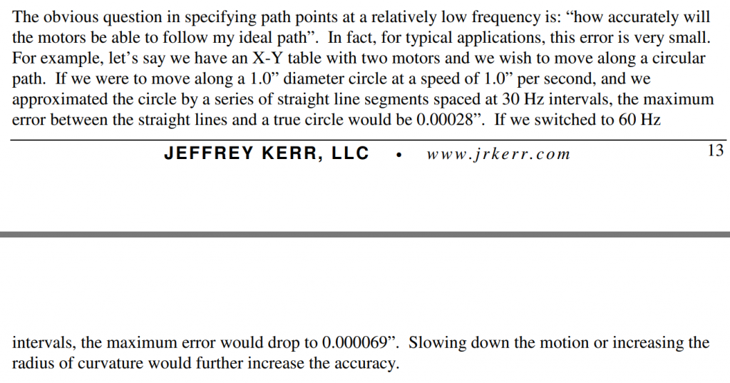 |
||||
| Volhout Guru Joined: 05/03/2018 Location: NetherlandsPosts: 3552 |
Maybe I am not into 3D machining as most of you, but as far as I know the workflow is as follows 1/ a design is created 2/ machining files are generated 3/ the machine file is sent to the cnc machine 4/ the machine executes the instructions 1,2 are outside the capabilities for a cmm2, this is the terrain of pc’s 3 is doable by cmm2, but also CMM1 or picomite. This also includes machine setup and alignment. 4 is best performed by well designed machine control processors, such as GRBL Please understand the 90% of all chinese cnc machines and 3d printers use this GRBL open source software. It is not a toy. Volhout Edited 2024-04-14 07:14 by Volhout PicomiteVGA PETSCII ROBOTS |
||||
| Page 1 of 2 |
|||||
