
|
|
Forum Index : Microcontroller and PC projects : Caravan Battery Monitor Mk II
| Page 1 of 2 |
|||||
| Author | Message | ||||
| panky Guru Joined: 02/10/2012 Location: AustraliaPosts: 1098 |
Hi Folks, After about a year of good operation in my caravan, I decided to tidy up and upgrade my Caravan Battery Monitor System. The existing current monioring system is not as accurate as I would like and also a bit clunky as it's layout. I have now used Allegro ACS758 hall effect current sensors and used the CG CMM2 as the base system. There are four files attached - a read me, the actual .BAS file and a couple of pictures. Any questions are welcome. For Hugh, can you kill the existing library entry of the Battery Monitor and if you choose to, include this one. Cheers, Doug. 

2013-05-13_080122_CVBM204.zip ... almost all of the Maximites, the MicromMites, the MM Extremes, the ArmMites, the PicoMite and loving it! |
||||
centrex Guru Joined: 13/11/2011 Location: AustraliaPosts: 320 |
Hi Doug Excellent work, but can you provide a picture of the current sensors and what size monitor you use. regards cliff Cliff |
||||
| paceman Guru Joined: 07/10/2011 Location: AustraliaPosts: 1328 |
Yes, very nice going Doug. Why the 22v scale on the running display and also what do you estimate the overall accuracy is (i.e state of charge), say over 24 hours? Also, how do you "zero" the state of charge to stop cumulative errors? Greg |
||||
| shoebuckle Senior Member Joined: 21/01/2012 Location: AustraliaPosts: 189 |
Hi Doug, I will replace the .BAS and readme.txt files in the library. Do you want the circuit diagram removed as well? It is no problem to leave it there if it is still relevant. Cheers, Hugh |
||||
| panky Guru Joined: 02/10/2012 Location: AustraliaPosts: 1098 |
Hi All, Cliff - picture of the current sensors attached. These are Hall Effect devices with one in the charging side earth lead (solar, 240VAC) and one in the load earth line with the junction of the two being the battery earth. I will knock up a schematic tonight for you. 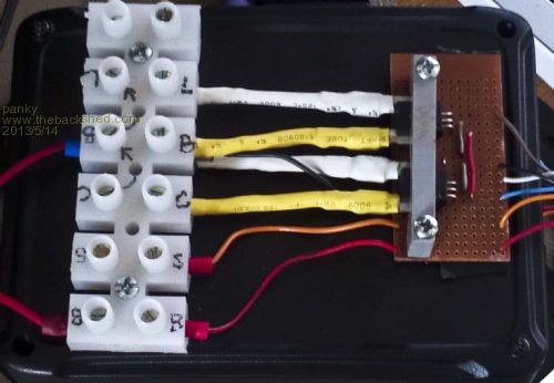
Input current sensor on the bottom, load current sensor on the top. If you use these devices, be very, VERY carful of the secondary leads - they are VERY fragile hence the clamp on the top. The care is worth the effort as they are extremely simple to use and very accurate. Two other wires on the bottom are battery 12V and solar panel (up to 22V), both of which are scaled down inside to 0 to 2.5V full scale and fed to analogue inputs on the CG CMM2. The display I use in the van is a little 7 inch job with a VGA input that I got from Hong Kong for A$89. Similar to units by other forum members. Greg - the 22V scale on the running graph is for both battery voltage and solar panel voltage (actual panel output). Accuracy of the input and load currents should be better than + or - 0.5Amps over a 24 hour period. The days running amp hour numbers are directly calculated from the amps above. As to charge, this is an area where I had to use some guesswork and rule of thumb calculations. I keep two days worth cumulative amp hour input and output and my main concern as a 'vanner is "do I put in more each day than I take out?" In fact due to losses etc. the general ROT is put back at least 10% more than you use. Also, an unloaded, charged battery should measure around 12.75 to 12.8V and stay stable at this level for at least 24 hours. So every few months, I fully charge the battery, measure and determine the general state of the battery. From there, I use the rule above - put back more than you take out plus a bit more. As a general result then I can rely on the actual battery voltage under light load to indicate the average state of charge. I choose to try to cut battery usage totally at around 12V which equates to about 30% remaining charge to save the battery. Purists may feel this is a bit low and I use it as my worst case. My configuration has 400W of solar so if I get some decent sun, I can put back in better than 50amphours most days so this (currently, until I can convince SWMBO that I need some more solar  ) limits my nightly usage to somewhere around 45 amp hours. ) limits my nightly usage to somewhere around 45 amp hours.
As an emergency, I have a generator as backup but have only used it twice in four years (8 months of the year) on the road where I normally do 4-5 free camping followed by 1-2 in a park to top up power, water etc. I have an excellent treatise on batteries which I will dig out and post later. Hugh - feel free to leave the old schematic although it has been superceded by this current incarnation. Cheers, Doug. ... almost all of the Maximites, the MicromMites, the MM Extremes, the ArmMites, the PicoMite and loving it! |
||||
| panky Guru Joined: 02/10/2012 Location: AustraliaPosts: 1098 |
New schematic for Cliff. 2013-05-14_093308_CVBM204.pdf Battery primer for Greg. 2013-05-14_093432_battery_primer.zip Cheers, Guys, Doug. ... almost all of the Maximites, the MicromMites, the MM Extremes, the ArmMites, the PicoMite and loving it! |
||||
| paceman Guru Joined: 07/10/2011 Location: AustraliaPosts: 1328 |
That's quite a tome Doug - I've given it more than an hour now and still only half-way through. Very good reading though - I've sent a copy to my mate who's just started off on a six month trip with a brand new van. He'll probably only read it for ten minutes, but then at least I can tell him he didn't follow good procedure if he complains to me :-) I wouldn't mind setting him up a system like yours in the long term so thanks for all your effort. The penny's beginning to drop re "state-of-charge" for me now; I hadn't realised it was necessarily sort of "vague" (input - output, then "normalise" somehow over some sensible time period). The need for a logging/display system like you've done is becoming clear! BTW where do you get the shunts that feed the Hall sensors? Greg |
||||
TassyJim Guru Joined: 07/08/2011 Location: AustraliaPosts: 5915 |
The ACS758 has the shunt built in. I am on the road for a few months at the moment but a few problems meant that I did not have time to get my monitor system up and running before I left. I had trouble holding a mouse, a soldering iron was a definite no-no. I have the sensors installed and a maximite with me but no easy way to join the two.... Jim VK7JH MMedit MMBasic Help |
||||
| paceman Guru Joined: 07/10/2011 Location: AustraliaPosts: 1328 |
Ah ha, - thanks Jim I'm definitely learning here. I've just noticed Glenn has an article on the front page of TBS about using the Allegros, and photos about mounting them. If I'd looked earlier it would have been self evident. After reading that it seems using the two unidirectional ones like Doug has is the way to go. I checked the Element14 website too for current pricing; they have them now for $10 to $14 depending on "model". Greg |
||||
| centrex Guru Joined: 13/11/2011 Location: AustraliaPosts: 320 |
hi Doug Thanks for the info, I have used the same current sensor but I recessed mine into a pcb so all pins were soldered down no problem with fragile pins. Using this sensor certainly reduced the complexity of your origonal system. 
regards cliff Cliff |
||||
| panky Guru Joined: 02/10/2012 Location: AustraliaPosts: 1098 |
Hi Cliff, PCB mount is definately the way to go as you have done. PCB designing is still on my to do list - I have been playing with Design Spark a bit to get familiar. For Tassie Jim - the interface from the ACS758 to the MM couldn't be simpler - just feed earth and 5v back to the ACS758 and take the Viout pin into an analogue pin on the MM. The only slightly fiddly bit for the unidirectionals is to calculate the offset. I wrote a simple little loop that sampled the pin and averaged the value then stepped the offset down from .8v down in 1mV until zero. This then became the offset I used in the main program. Mine worked out to 582mV. Cheers, Doug. ... almost all of the Maximites, the MicromMites, the MM Extremes, the ArmMites, the PicoMite and loving it! |
||||
| centrex Guru Joined: 13/11/2011 Location: AustraliaPosts: 320 |
Hi Doug In one of your posts you mention you have 400watts of solar panels, if this is correct the caravan must be one very large solar panel. regards cliff Cliff |
||||
Wombat Regular Member Joined: 27/05/2011 Location: AustraliaPosts: 72 |
I will have to put this on my 'to do' list 
How far away, or rather, how long can you make the leads from the sensor to the Maximite? Or is that what the offset adjustment is for? Russ P.S. How would it be feesable converting to a digital output  |
||||
| panky Guru Joined: 02/10/2012 Location: AustraliaPosts: 1098 |
Hi Cliff, I have three panels - an 80W, a 120W and a 200W, all nominal 12V. These give me around 20V at the input to the solar controller at full sun, midday, mid summer and at about 18A via the solar controller into the battery. I plan to upgrade the 80W unit to a 200 to 250W unit when I can afford to. The issue is that with the panels flat on the roof of the van, there is considerable fall off before and after noon and also that "lovely spot under the trees by the river" pointed to by SWMBO just doesn't really cut it
For Russ, the offset is based on the fact that the ACS758 works on 0 to 5V (actually down to 3.3 Vcc but they recommend 5V for Vcc for max accuracy). Thus, the internal circuitry can not go right down to 0V but about a diode junction above ie. about 0.6V - the offset ( for the unidirectional version - the bi-directional device, uses split supplies and works either side of 0V to show current direction). As to lead lengths, with suitable decoupling, I can't see why you couldn't go out to a meter or two but there is no mention in the specs that I can see. Cheers, Doug ... almost all of the Maximites, the MicromMites, the MM Extremes, the ArmMites, the PicoMite and loving it! |
||||
| centrex Guru Joined: 13/11/2011 Location: AustraliaPosts: 320 |
Hi Doug Can you send me the complete part number for the particular current sensor that you are using and where you purchased them from. How do you find the accuracy of the various readings in particular the battery volts and current as everything has large dividers in the system. Your caravan is quite a power house with all the panels that you have. Regards cliff Cliff |
||||
| panky Guru Joined: 02/10/2012 Location: AustraliaPosts: 1098 |
Hi Cliff, The current sensor is an ACS758LCB-050U-PFF-T unit, a 50A unidirectional formed lead version. I'm away from home at the moment but I am pretty sure I got them from Element14 (farnell). The voltage readings at the MM pin seem to drift up to +/- 10mV - probably a function of noise, drift and the divider system. For this reason, I take 20 readings and average them. As I aim an accuracy of +/- 10mV, the averaging seems to fit the bill. I have checked the accuracy with a decent quality 5 digit multimeter and it lines up pretty good, certainly enough for my usage in this case. My aim with the caravan power was to be able to get by each night without having to use my generator (they can be quite annoying if you are sitting back enjoying the peace and quiet ) and have enough panel acreage to recharge next day given reasonable sun.
Attached is an updated version of the software that corrects a bug in the running graph area, adds a simulate option so you can run it without any inputs on a colour MM to see how it works and adds a 4 day charge in/out amphour history value. 2013-05-22_041324_cvbm206.zip Cheers, Doug. ... almost all of the Maximites, the MicromMites, the MM Extremes, the ArmMites, the PicoMite and loving it! |
||||
| paceman Guru Joined: 07/10/2011 Location: AustraliaPosts: 1328 |
Doug, how do you manage to read all that on a 7" screen? I've been running your new simulation for a couple of hours now on a 23" screen and it's pretty "busy" even on that. Would it be a major drama to be able to incorporate a press-button or knob to quickly be able to switch between say, three or four different screens that showed various blocks of the full display and have it running normally on the most important one? That way you could read it on the wall while sipping your morning coffee! I originally had in mind using one of the little cheap 3.5" composite displays driven via a VGA to composite converter but that's probably downsizing just a tad too much! I think your 7 incher is more what's needed.  I did actually get a cheap 3.5" screen (~ $25) and that VGA to composite converter (~ $12, both free postage) and it works very well, full MM colour on composite! The converter for that price is amazing - pity it isn't available with just the two big chips doing the work so that it would all be easily box-able. I did actually get a cheap 3.5" screen (~ $25) and that VGA to composite converter (~ $12, both free postage) and it works very well, full MM colour on composite! The converter for that price is amazing - pity it isn't available with just the two big chips doing the work so that it would all be easily box-able.
BTW, I checked Element 14 and they do have the current sensors. Currently only three in stock here in Oz ($14 each) but plenty with their usual 6-7 days ex UK delivery. Greg |
||||
| graynomad Senior Member Joined: 21/07/2010 Location: AustraliaPosts: 122 |
We have over 1700W of solar panels and 14 220Ah batteries in our motorhome, and where we are parked at present STILL have to run the gennie for a while every day. Rob Gray, AKA the Graynomad, www.robgray.com |
||||
| centrex Guru Joined: 13/11/2011 Location: AustraliaPosts: 320 |
Hi Doug Tried the simulation on a 19in screen looks very good but as the Graynomad commented it would be rather busy on a 7 in screen what you get used to I suppose and what info you are looking for. Graynomad you do have a lot of power must not be parked in a sunny spot. Regards Cliff Cliff |
||||
| panky Guru Joined: 02/10/2012 Location: AustraliaPosts: 1098 |
Greg, Yes, the display is pretty busy - I am working on a version to do exactly as you suggest - multiple screens, probably all at font #2, selectable from inside the van. Rob, that's some system! Am I right in assuming a 24V system? If so, you must use a great deal of power each night? By my back of the envelope rough calculations, 14 by 220ahr batteries ( I'm guessing configured as 7 banks of 24V. This would very roughly equate to 16KW of available power ( taking the batteries no lower than 50%). If you used all this 16KW each night, you would need to put back in at least 800amphours. Your solar system could provide around 40amps at max sun using an MPPT (max power point tracking ) solar controller so the best you could recover under normal conditions would be somewhere around 5 hours at average 20 amps ( very rough calculations) soooo, you SHOULD be able to to get most of your nightly usage back from solar. Edit: Way off here - looks like you might only be putting 100 or so amp hours back in, so if you are using a lot of you available battery power, your solar won't be enough. Just letting my imagination wander as to your system - real calculations are more complex, taking into account power usage over the day, actual solar input etc. This was the reasons behind my original creation of the battery monitoring program - I wanted real data on the gozintas and gozoutas
Cheers, Doug. ... almost all of the Maximites, the MicromMites, the MM Extremes, the ArmMites, the PicoMite and loving it! |
||||
| Page 1 of 2 |
|||||
