
|
|
Forum Index : Microcontroller and PC projects : Caravan Battery Monitor Mk II
| Author | Message | ||||
| graynomad Senior Member Joined: 21/07/2010 Location: AustraliaPosts: 122 |
Greg and Doug, Yes our system is pretty large for a motorhome, probably 80% of the roof is panels. Of course being winter doesn't help, but we are currently parked on our land in central QLD and the best spot to park just happens to be shaded for about half the day, not much we can do about that so we run the gennie. Yes. We are both up until 2 or even 3AM, with with laptops burning (I have two screens) and the TV for at least 2-3 hours a night. Then there are two compressor fridges running and for a while before bed time the electric blankets. Also the heater which is diesel but still has a 12v blower. The voltage seldom gets below 24.6, what that is in SoC terms I don't know because I don't have a monitoring device to tell me that. In summer and a sunny spot we have no problems as you would hope with such a system, it's mostly the shade that's the problem at present. I recent swapped 8x 64W Unisolars with 4x 250W + 2x 100W no-names, that has worked well. I calculated a max of 51A from all the panels (there are others as well), I don't sit and watch the display but I have seen 48A on a couple of occasions so my cals were close enough. Yes you need to know what's what. I am also working on a system, mine is based on an Arduino Due clone and a series of monitoring nodes connected with a CAN network. I just finished the main CPU design and am currently working on a system of isolated nodes to measure individual battery voltage on a string of batteries. I might start a thread about this to see if you guys have any ideas about what such a monitoring system should do. ______ Rob Rob Gray, AKA the Graynomad, www.robgray.com |
||||
| panky Guru Joined: 02/10/2012 Location: AustraliaPosts: 1098 |
Rob, Sounds like you have it worked out pretty well. With my 12v system, 12.75v under load indicates a fully charged system dropping to 12.2v equalling ( roughly ) a 50% charge so your 24.6v should equate to roughly 55 to 60% charge. All the doco I have read is that going below 50% even intermittently should be avoided as it can greatly reduce battery life. Re measuring all the individual batteries in a series parallel bank is an interesting problem - one that I am working on also - will post and pool experience as I go. You might like to have a look at the article on batteries I posted on page 1 of this thread - lengthy but informative. Cheers, Doug. ... almost all of the Maximites, the MicromMites, the MM Extremes, the ArmMites, the PicoMite and loving it! |
||||
TassyJim Guru Joined: 07/08/2011 Location: AustraliaPosts: 5915 |
In the past I have measured the halfway point and compared it to the full voltage. If it isn't close to exactly half, you know you have a problem with a cell. It doesn't tell you which cell but a good compromise for logging purposes. You also have to advantage of ground referencing which removes some complications. Jim VK7JH MMedit MMBasic Help |
||||
| graynomad Senior Member Joined: 21/07/2010 Location: AustraliaPosts: 122 |
Lower than I would like TBH, especially as this is every night. Stop working, I've got it sussed (I think), any number of 2, 6 or 12v batteries up to 100s of volts for the bank. I've started a PCB design but have other projects to do first. Yes I read bits of it and saved for future reference. I'm an EE but batteries are still a black art for me :) Yes that helps a lot, it starts to get messy if you have say a 48 or 96v system with varying numbers of batteries, a ground-based system is OK as a one-off for a particular layout but is not very scalable for all types of battery arrangements. My design has a node per battery, the location of the battery in the string is of no importance to the node, the master displays the data appropriately. You can also measure up to 3 temperatures per battery, nominally this would be for the two terminals and the body. Rob Gray, AKA the Graynomad, www.robgray.com |
||||
centrex Guru Joined: 13/11/2011 Location: AustraliaPosts: 320 |
Hi Doug The Graynomad's system sounds huge, I have 1.7kw of panels on the roof of my house and it takes up a lot of space. Back to your software ver206 I note you multiply the two readings from the current sensors by 16.667 I assume this is to get the correct current readings. I also wonder why in the simulation mode you don't set the false numbers and then jump straight to the display mode. Also is there any reason why you don't get all the data in one for next loop other than it is easier to debug. Would you be kind enough to send the circuit of the voltage dividers as I want to make a PCB of the system, I have my own ideas of how it should be and to compare notes. Regards Cliff Cliff |
||||
| panky Guru Joined: 02/10/2012 Location: AustraliaPosts: 1098 |
Hi Cliff, The current sensors I have used have an ouput sensitivity of 60mV per amp so sensor output ranges from 0V (0A) to 3.0V (50A). Thus to translate the sensor voltage reading to a numeric value represeting amps, I need to multiple the voltage reading by 16.667 to convert to amps. As to the simulate values, I didn't want to disrupt normal program execution, just an alternative when there are no real inputs. I don't understand your question on collecting the data in a for/next loop? The overall program separates data collection from data processing. Collection is done by an interrupt routine triggered every 2 seconds. The interrupt routine also sets flags to indicate2 second rollover, 1 minute rollover, 1 hour rollover and end of day ( actually 6 AM ) rollover. The data processing involves waiting for the newdata flag which indicates a 2 second interrupt has ocurred and thus new data is available. The program then proceeds through 2 second processing, then checks and processes minute, hour and eod data as applicable and finally returns back to the main loop waiting for the next newdata flag. I'm no expert prorammer but it seemed a logical sequence for me to use. The resistive dividers used were extremely simple - as the battery voltage ranges from around 11v min to 14.5v max, I chose to have 0V to 15V equate to 0V to 2.5V via a 6:1 resistor divider. Same for the solar panel voltage except now input voltage ranges from 0V to 25V so divider is 10:1. In both cases I used 2 resistors plus a small value pot to allow exact calibration. Cheers, Doug. Edit: Cliff, if you are doing solar on your house roof, you might be interested in a solar calculator I wrote on the solar forum under the thread Solar Power. Cheers, Doug. ... almost all of the Maximites, the MicromMites, the MM Extremes, the ArmMites, the PicoMite and loving it! |
||||
| centrex Guru Joined: 13/11/2011 Location: AustraliaPosts: 320 |
Hi Doug If you have a look at this you will see what I get from the panels when the Sun gets above a tree, at the moment I am in credit to the power company. http://www.users.on.net/~lwyl5744/pwr/index.htm What I meant with the code is to put it all in one loop as below not that it matters......... GetData: ' Timer Interrupt handler ' Arduino analogue input pins SetPin a0,1 ' pin 35 - battery voltage - 0 to 2.5V = 0 to 15V SetPin a1,1 ' pin 36 - solar volts - 0 to 2.5V = 0 to 25V SetPin a2,1 ' pin 37 - input current shunt - 0 to 2.5V = 0 to 50A SetPin a3,1 ' pin 38 - load current shunt - 0 to 2.5V = 0 to 50A ' Get the battery voltage If Simulate = 1 Then BVolts = 13.6 SVolts = 16.5 InputCurrent = 18.3 LoadCurrent = 7.2 else ic=0 BVolts = 0 GetPin35 = 0 SVolts=0 GetPin36 = 0 InputCurrent = 0 GetPin37 = 0 LoadCurrent = 0 GetPin38 = 0 'BatteryVolts For ic = 1 To 20 GetPin35 = Pin(a0) BVolts = BVolts + GetPin35 'SolarVolts GetPin36 = Pin(a1) SVolts = SVolts + GetPin36 'InputCurrent GetPin37 = Pin(a2) - 0.5817 InputCurrent = InputCurrent + GetPin37 'LoadCurrent GetPin38 = Pin(a3) - 0.5803 LoadCurrent = LoadCurrent + GetPin38 next BVolts = BVolts/20 ' Average out Battery voltage BVolts = BVolts*6 ' 15 battery volts = 2.5 MM volts SVolts = SVolts/20 ' same as for BVolts SVolts = SVolts*10 ' 25 solar volts = 2.5 MM volts InputCurrent = InputCurrent/20 ' Average out input current InputCurrent = Abs(InputCurrent*16.667) ' Correct for opamp amplification LoadCurrent = LoadCurrent/20 ' Average out load current LoadCurrent = Abs(LoadCurrent*16.667) ' Correct for opamp amplification endif ' Get the current time, extract the minutes component I have tried this and it works in sim mode, I am no programmer I fix aeroplanes (Gliders to be precise) regards cliff Cliff |
||||
| centrex Guru Joined: 13/11/2011 Location: AustraliaPosts: 320 |
Hi Doug Another question these are just of my general interest in electronic things as I do not have a van of any description. I do have 3 x 60w watt panels that supply power to my computer system. The question do you use the dual function of the Ctek D250S to charge the van battery while on the road. regards cliff Cliff |
||||
| centrex Guru Joined: 13/11/2011 Location: AustraliaPosts: 320 |
Hi Doug I have decided to use your you beutt monitoring software to look at what my 3x60 panels that charge a large valve regulated battery bank get up to. I am not a vero board person I find it easier to make a PCB, so using your ideas here is a picture of the board it is double sided but not plated through. I am still awaiting the current sensors. 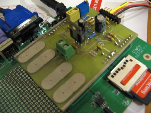
Many thanks Cliff Cliff |
||||
| panky Guru Joined: 02/10/2012 Location: AustraliaPosts: 1098 |
Hi Cliff, Sorry for the delay in responding - I've been on the road and it's easy to miss responses. Thanks for the suggestions on the interrupt handling - I'm working on an updated version which has a more readable display and also uploads data to an Anroid tablet via bluetooth. I have the bluetooth module working to the tablet ( module is a JY-MCU serial to bluetooth ) and need to complete the tablet code end in dr Basic! to display the data. Regarding question on the CTEK 250S, I haven't yet used it in the dual input mode but plan to soon. I do have some concerns on how the CTEK differentiates between solar and vehicle inputs and which gets priority or whether they aggregate - I have asked CTEK but they were not helpfull at all so I am still in the dark on exactly how this box works. Love your PCB  - any chance of a layout diagram? I have played around a bit with Diptrace and need to do more. - any chance of a layout diagram? I have played around a bit with Diptrace and need to do more.
Regards, Doug. ... almost all of the Maximites, the MicromMites, the MM Extremes, the ArmMites, the PicoMite and loving it! |
||||
| centrex Guru Joined: 13/11/2011 Location: AustraliaPosts: 320 |
Hi Doug Here is a picture of the finished pcb, I have sent a pm re this. 
regards cliff Cliff |
||||
