
|
|
Forum Index : Microcontroller and PC projects : MM and AC mains power control
| Author | Message | ||||
Blackened Regular Member Joined: 11/08/2012 Location: AustraliaPosts: 66 |
Hello all, I'm after some input regarding proportional control of AC mains devices. I use a SSR to control a heating element using PWM on a 3 sec cycle. That's all good and working as intended, but I'm wondering how I might control a 240V pump? What sort of data do I need to know about the pump, in order to figure out what type of control is suitable (or even possible) for it? Obviously I can't use a 3 second cycle. Would PWM work at all, even on a shorter cycle time? I'd prefer some sort of proportional control. I found these variable SSRs on ebay. Is there a simple way to interface it with the MM? I don't know enough about electronics to figure it out. I have some vague notions but no real clue. Thanks for any and all help Peter |
||||
crez Senior Member Joined: 24/10/2012 Location: AustraliaPosts: 152 |
Peter, Most pumps use induction motors, which don't cope well with reducing the speed by varying the average voltage fed to them. A more complicated system is used which re-creates the AC supply voltage but at a reduced voltage AND reduced frequency. This is known as a 'variable speed drive'. There was a project in Silicon Chip magazine for a pool pump speed control in the last 2 years that ran on this principle. David |
||||
| crez Senior Member Joined: 24/10/2012 Location: AustraliaPosts: 152 |
Peter, If you have a serious application, there are VSD's on Ebay that have serial control( rs232 or rs485 ) that would interface with a MM. Alternatively, some types use an analog DC voltage input to control the motor speed. This analog DC could be controlled by the MM PWM output. David |
||||
| Blackened Regular Member Joined: 11/08/2012 Location: AustraliaPosts: 66 |
Thanks David, your info is greatly appreciated. I've been googling now that I have some sensible keywords  . My purpose isn't serious enough to spend up big. I did have a look on Ebay and including postage it looks like $130 ish is entry level. I think I'll simply use a motorised ball valve until VFD/VSDs become more affordable. I like the level of control they offer, and frankly it rubs me the wrong way to run a pump at full power and choke off the flow. It's like hammering in a screw instead of using a screw driver . My purpose isn't serious enough to spend up big. I did have a look on Ebay and including postage it looks like $130 ish is entry level. I think I'll simply use a motorised ball valve until VFD/VSDs become more affordable. I like the level of control they offer, and frankly it rubs me the wrong way to run a pump at full power and choke off the flow. It's like hammering in a screw instead of using a screw driver  but it will get the job done and for a lot less$. but it will get the job done and for a lot less$.
So is PWM really only useful for resistive loads? |
||||
belsean21 Newbie Joined: 06/07/2013 Location: AustraliaPosts: 12 |
Peter, Your SSR is probably a variation on a TRIAC phase switching circiut These work fine controlling AC heating elements, dimming lights, and some universal type AC motors. Heres an simple example suitable for use with the MM. However, 240V pumps are usually induction type motors and can't be controlled in this way. SiliconChip have published a number of motor speed controller projects over the last few years that may find useful SiliconChip April 2012 - 1.5kW Induction Motor Speed Controller, Pt.1 SiliconChip May 2009 - 230VAC 10A Full-Wave Motor Speed Controller SiliconChip February 2009 - 10A Universal Motor Speed Controller, Mk.2 Cheers, Sean |
||||
| Blackened Regular Member Joined: 11/08/2012 Location: AustraliaPosts: 66 |
Thanks Sean! I'm using a simple SSR, and the MM pulses the relevant pin for a predetermined portion of a 3 second cycle. A very wiiiide pulse width LOL. Good enough for what I need. The 3 second cycle seems to be adequate as the thermal mass of the element evens out some of the fluctuations. A bit like a one of those bi-metal simmerstats, only they tend to run a very long cycle that isn't appropriate. As you can see, I'm looking for simple solutions, cos I'm a simple kinda guy 
I don't think that the silicon chip controller would be beyond my ability, but even that is more money than I'm willing to spend at the moment. It's not a "must have" for this project, there is still money to spend on other things that I need yet.... Ok, for the pump, what about something that would allow me to switch between 1 or 2 motor speeds, rather than an infinitely variable drive? Maybe this could be achieved in a more simple fashion? Often things like halving or quartering can be achieved by methods quite different to xx%. Visually, I'm imagining the following: take a 50hz mains current, "delete" every second cycle, and "stretch" the remaining cycles to get 25hz. So you'd get 25hz at 50% power. I'm not very good with electronics, no doubt many of you are giggling at my suggestion and probably rightfully so!! But I do try.... |
||||
| belsean21 Newbie Joined: 06/07/2013 Location: AustraliaPosts: 12 |
The speed of an induction motor is related to the mains frequency or some fixed multiple of that frequency. In simple terms a VSD or induction motor speed controller is an oscillator feeding into a 240V power amplifier. Vary the oscillator frequency and you vary the frequency of the 240V AC waveform and thus the motor speed. The easy part is generating an AC sinewave between 1 & 50Hz. You could use a 555 timer & opamps or any microcontroller. The power circuit is the more difficult of the 2. The SiliconChip article referenced earlier will provide info on how to design & build the power circiut. Deleting whole cycles from the AC waveform is certianly possible. Look up zero crossing detectors for more on approach. However I've never seen it used with motors. I'm no expert here, but I doubt it would work. I cant think of an easy way to strech the remaining cycles out to cover the waveform gaps. It would be simpler to adopt the VSD approach. Hey, we all had to start somewhere. The best way to learn is have a go and ask questions. Remember, they only dumb question is the one you don't ask. Because you can be sure that someone else is wondering the same thing. Sean. |
||||
palcal Guru Joined: 12/10/2011 Location: AustraliaPosts: 1805 |
Instead of using the motorised valve to choke off the flow which will load the pump why not use it in a bypass pipe to shunt some of the flow back to the suction side of the pump. Palcal. "It is better to be ignorant and ask a stupid question than to be plain Stupid and not ask at all" |
||||
| robert.rozee Guru Joined: 31/12/2012 Location: New ZealandPosts: 2291 |
good idea Palcal! what volume of (i presume) water are you looking at pumping? what is the application? for domestic house installations i've seen a sealed reservoir tank used, with a pressurized air bladder inside. the pressure in the system is then used to turn the pump on and off every few minutes via a simple pressure switch. when the pressure drops below a minimum level, the switch turns on; when the pressure goes above an upper limit, the switch turns off. you could emulate this for a small installation (lie a water feature) using a car tyre inner tube as your reservoir. the pressure could be sensed using a cheap analog air pressure sensor hooked up to your mm/arduino/etc. |
||||
| Blackened Regular Member Joined: 11/08/2012 Location: AustraliaPosts: 66 |
I'll be pumping small volumes up to maybe 10 litres/minute. It's for a recirculating heat exchanger system for all grain beer brewing. It needs to be a continuous steady flow rather than on/off. Oh and air in the circuit is undesirable. The pump head is magnetically coupled and centrifugal, so reducing the outflow isn't really a big issue I wouldn't think? So what advantage is gained by diverting some of the outflow back into the inflow, as compared to restricting the outlet? The fluid either flows around an external circuit and back in, or simply circulates within the pump head and fails to exit? Or am I missing something? |
||||
| JohnS Guru Joined: 18/11/2011 Location: United KingdomPosts: 3669 |
Do you need a mains voltage pump? Would a low voltage DC pump be better? I'd make sure to have redundancy (cheap extra sensors) and a sure way to prevent overflow/overheat, if such would be possible. John |
||||
| robert.rozee Guru Joined: 31/12/2012 Location: New ZealandPosts: 2291 |
aha, now beer may present a few extra problems. firstly, diverting outflow back to the inlet will reduce the load on the pump, while also reducing turbulence around the pump's blades. if the pump is running warm, this may be a necessary option. but in pumping beer (a foodstuff) itself, there may be other factors involved. it may be that it is desirable to avoid this excessively mixing of the beer while it is pumped, which would dictate needing to slow down the pump itself. a simple option may be to build a small inverter, that runs off 12 volts and produces 230v ac output. if the pump is small, this could be accomplished with a normal 12 volt mains transformer, connected in reverse and driven by an H-bridge. the H-bridge can then be controlled by your computer, that sets the switching speed, be it 50Hz, 30Hz, or even lower. at low power levels there will be little issue of running at such a low frequency. or you may be able to tinker with the magnetic coupling, to achieve some slippage and slow the pump down. |
||||
| BobD Guru Joined: 07/12/2011 Location: AustraliaPosts: 935 |
caravan fresh water pumps and boat bilge pumps run on 12 volts. Cheap enough on eBay and elsewhere. Bilge pumps are often fully submersible. Caravan pumps have automatic over pressure shut off if the line gets blocked. |
||||
| Blackened Regular Member Joined: 11/08/2012 Location: AustraliaPosts: 66 |
As some have mentioned, a 12v pump would have been the better choice for a micro-controlled home brew project. However I bought this pump more than a year ago with the intention of a standard, manually operated setup. There are magnetically coupled 12vDC pumps available that are food grade and heat tolerant (80C+) and frankly it looks like I should buy one and give up on the 240V unit I have. Again, this isn't critical to my project, which is really only in it's infancy. At some point in the future, pump control will be a priority to spend some money on, but in the short term I was hoping for a cheap work-around that was a bit better than using an electric valve. You've all been really helpful so far! Thanks everyone
Ah! This sounds achievable Robert. Googled "H-Bridge". They swap/toggle the output polarity yes? This would feed a square wave into the transformer? And would this even be a concern for a 240v 20W pump? I'm learning! hehe. A quick look at Ebay has some really cheap h-bridge stepper controllers rated at 800mA, would these be a suitable interface between the MM --> transformer --> pump? I guess I'll need to read up about these controllers a bit more yet. Not sure how the output is directed by the controller just yet. I'm only brewing maybe once a month, and the pump will only be used for 2-3 hours at a time so it's not exactly getting a thrashing. |
||||
| robert.rozee Guru Joined: 31/12/2012 Location: New ZealandPosts: 2291 |
you have the right idea. since the H-bridge is controlled by a computer, you don't need to use exactly a square wave drive - you can have 'off' intervals between switching polarity to achieve a drive into the transformer that is a little closer to a sine wave. for example 40% (of the cycle) positive, 10% off, 40% negative, 10% off. this is called a 'modified sine wave': 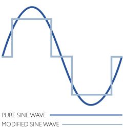
the transformer, by the nature of the beast, tends to knock the corners off the signal being passed through it, resulting into an output going to the motor that is a not-too-bad approximation of the AC mains in terms of shape. assuming the low load you are presenting (20w) the motor will be none-the-wiser about what is going on. |
||||
| Blackened Regular Member Joined: 11/08/2012 Location: AustraliaPosts: 66 |
That is some most excellent information thanks Robert. So many keywords, so little time!!
What would be an approximate lower limit on the frequency I could run it at? Try it and see? Or could I do damage under certain circumstances? |
||||
| robert.rozee Guru Joined: 31/12/2012 Location: New ZealandPosts: 2291 |
i'd say you could make it down to perhaps 15Hz without too many issues. the level of power you are dealing with is very small, so i can't see there being any major risks of damage. the lower limit is set by the transformer losing efficiency, and the motor in the pump starting to 'slip'. just experiment and see... |
||||
