
|
|
Forum Index : Microcontroller and PC projects : CGMMSTICK1 & RTC
| Author | Message | ||||
pcaffalldavis Senior Member Joined: 17/10/2011 Location: United StatesPosts: 187 |
I've been away for a few months. I'm so far behind I'm just now starting to play with my CGMMSTICK1's. Time for me to move forward from the original MM. I have a nice CG color MM too, but I need to know how to connect up a RTC PCF8563 to the CGMMSTICK1. On the original MM I connect this I2C RTC through I/O's #12 & 13 plus 3V & Grnd. I put the SDA through 12 and the SCL on 13. This configuration does not work on the CGMMStick1. I don't have a sheet for the CGMMSTICK1 and don't see a working link on the website to get one, but I think the MMIDE3 shows I/O's 15 & 16 are for sending and receiving data? I've tried these I/O's and others and cannot get the Clocread.bas & clockset.bas programs to work. Any pointers! I really like the CGColor MM but need to make the five CGMMStick1's I got over a year ago useful too. A RTC will do that for me. I'm getting ready for heating season number two for the MM controlled wood fired boiler. It worked great the first winter. I tweaked the program as needed through the first season. Now I'm making replacement component boards and configuring extra MM's so if something breaks or fails I will have spares to pop in and avoid down time. Pete in Hyder We're all here 'cause we're not all there. |
||||
BobD Guru Joined: 07/12/2011 Location: AustraliaPosts: 935 |
Pete, the info you want is probably in a document from CG's website called Beginning Maximite. I just tried to get it but I can't raise the website. Can anyone else get through? I had a look for his member name on TBS and couldn't find it either. ???? What may be stopping you is the datasheet for that chip says the address is A3 for read and A2 to write. Ignore this. For use in the Maximite the address is &H51 or decimal 81. You may have to modify the program to suit. I haven't read them but I'll have a look. It may take some time as we have football finals on here at this instant. |
||||
| pcaffalldavis Senior Member Joined: 17/10/2011 Location: United StatesPosts: 187 |
Thanks Bob. I've tried downloading the 17MB Beginning Maximite four times now from his web site and it always seems to stall at around 19 to 24KB. And the CGMMSTICK1 User Manual version I got was an incomplete one he was working on when he announced the CGMMstick would soon be available (Dec 2011). I asked for a complete version of the manual on Friday but have not heard back yet. I'm beginning to wonder if the Beginning Maximite PDF replaced the CGMMSTICK1 User Manual? Who knows. We're all here 'cause we're not all there. |
||||
centrex Guru Joined: 13/11/2011 Location: AustraliaPosts: 320 |
Just a thought do you have the pullup resistors 4.7K on pins 12 and 13. regards cliff Cliff |
||||
| BobD Guru Joined: 07/12/2011 Location: AustraliaPosts: 935 |
Pete I would stick to pins 12 & 13. I can't find in the Maximite library those programs you mention. I have sent you a PM with my email address if you want to send a copy of them my way I'll have a look at them. Bob |
||||
| pcaffalldavis Senior Member Joined: 17/10/2011 Location: United StatesPosts: 187 |
Centrex, I do not. They were not needed on the original MM. You think that is it? I'm using a RTC that was previously on a MM and today I breadboarded it to a CGMMSTICK1. It works fine on the MM but on the CG I get a "2" for timed out. Pete We're all here 'cause we're not all there. |
||||
| BobD Guru Joined: 07/12/2011 Location: AustraliaPosts: 935 |
Pete, I think Cliff is correct. You need pullup resistors somewhere. They can be on the Maximite or on the RTC board but you do need them. The original Maximite did not have pullup resistors on pins 12 & 13. Bob |
||||
| JohnS Guru Joined: 18/11/2011 Location: United KingdomPosts: 3669 |
Maybe try getting wget first (I think it's available for Windoze as well as Linux), then use wget -c http://.... and it'll retry partial files. John |
||||
| BobD Guru Joined: 07/12/2011 Location: AustraliaPosts: 935 |
John, I assume you are talking about CG's website being down? I tried http://www.downforeveryoneorjustme.com/www.circuitgizmos.com and it's not lookin' good. Bob ah, It's hit me, you are talking about the download. The website seems to be down or so far down it's almost out of sight. |
||||
| pcaffalldavis Senior Member Joined: 17/10/2011 Location: United StatesPosts: 187 |
I'm using the same clock program that is here in the group. I just named them clockset.bas and clocread.bas. It helps me remember which is for what. I'm using 12 & 13 and put two 10K resistors on like I did on the original MM (I forgot this was done as 12 & 13 were also used for other purposes). Now when I boot, set the date$ & time$, load Clockset.bas and run it I get 1. The program is set for 0=Ok, 1=nack, 2=timeout. I never did understand what nack meant. The RTC has a jumper for battery or VCC. It is set to battery like it was when this RTC worked on the MM. I also tried it on VCC and still get 1=nack. I am a bit puzzled now. It really looks like it should work. I jumpered the resistors between both the five volt leg and 12 & 13 and then tried putting them on the 3.3 volt leg. Same results both ways. Hum... Out of my depth. Wouldn't the I2C addresses in the clock set/read programs remain the same for both the MM and the CGMMSTICK1? Currently it is &h51 We're all here 'cause we're not all there. |
||||
| MicroBlocks Guru Joined: 12/05/2012 Location: ThailandPosts: 2209 |
I have an archived file of about one year ago. I think it is still the right file for your CGMMSTICK1. You can download it here: Beginning Maximite (Sept 2012 version) Too many sites just disappear, so i save everything i need locally and in a backup, just in case. Microblocks. Build with logic. |
||||
| pcaffalldavis Senior Member Joined: 17/10/2011 Location: United StatesPosts: 187 |
Thanks for the download TZAdvantage. That is what I need. I'll go read now. We're all here 'cause we're not all there. |
||||
| BobD Guru Joined: 07/12/2011 Location: AustraliaPosts: 935 |
Better to use lower value resistors and / or slow the speed down to 100K. NACK is Negative ACKnowledgement. It looks like you may connecting to the RTC but something is wrong. Stick to 3.3 volts for the pullup Read my first post, the address is &H51 From the MMBasic Manual (v4.4) page 48 |
||||
TassyJim Guru Joined: 07/08/2011 Location: AustraliaPosts: 5915 |
The cgmmstick1 should operate identical to the mono maximite. Have you updated the firmware? Are you sure that you have the right terminals? 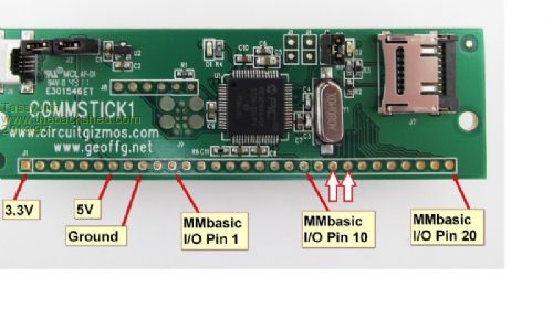
I have found the cgmmstick to be a very reliable board. Jim VK7JH MMedit MMBasic Help |
||||
| pcaffalldavis Senior Member Joined: 17/10/2011 Location: United StatesPosts: 187 |
I just tried a different RTC and it worked first time. I must have had a bad RTC. Its battery is still good so the chip must be bad. Into the dust bin and onward! Thanks all. Pete We're all here 'cause we're not all there. |
||||
| MicroBlocks Guru Joined: 12/05/2012 Location: ThailandPosts: 2209 |
Circuitgizmos.com is up again but i notice very large delays and errors when accessed from Thailand. I have a few servers in Europe and they can access it without problem. If you can not download the latest version from circuitgizmos "Beginning Maximite" i have a copy of it here: Beginning Maximite Microblocks. Build with logic. |
||||
CircuitGizmos Guru Joined: 08/09/2011 Location: United StatesPosts: 1421 |
Hi! Well I'm not sure what was happening over the weekend, but I didn't catch the CG website being down. Beginning Maximite can be found here: http://www.circuitgizmos.com/files/begmax.pdf http://www.circuitgizmos.com/files/begmax.pdf Micromites and Maximites! - Beginning Maximite |
||||
