
|
|
Forum Index : Microcontroller and PC projects : Micromite climbs the stairs
| Author | Message | ||||
| Keith W. Senior Member Joined: 09/10/2011 Location: AustraliaPosts: 118 |
My house has a downstairs Den with my computer and television. I desire lights for the stairs. Presently lights waste power in the lounge/dining room above. The builder/woodworker/ antique-restorer who built and lived previously in the house, when adding the Den, had created for himself a polished Mahogany posted staircase as a Christmas project. Small flush mount LED lights in the wall adjacent the steps will not spoil the carpentry on the opposite banister side and are to light up only when the stairs are used. My Micromite based system will control the 8 LED lights evenly spaced beside the stairs. �Infrared Remote Controller� sensors will serve as barrier detectors at the top and bottom approach. The two Micromite PWM outputs gated together with a resistor and diode generate the constant modulated 36KHz waveform required to drive the Infrared barrier LEDs. Approaching the stairs will trigger the lights to turn on progressively upwards or downwards depending on which sensor, and then turn off progressively upwards (or downwards) after a delay, and if both barriers are clear. Illumination is disabled during daylight as a consequence of a photo resistor exposed to ambient light level and connected to an analog input. The 12 volt lights supply may be powered down completely by the Micromite when not required, i.e. all lights off. A hidden switch will enable �Grandchildren Mode� that creates various light patterns. Remember �Kitt� from �Knight Rider�? A Console connector aids changes to the program or the light patterns and system logging. Rockby Electronics �Weekly Sale Specials� provided power MOSFETs, also dual MOSFET Drivers that boost the 3.3 volt Micromite outputs to drive the MOSFETs, Infrared LEDs and power supply control. These Drivers are capable of sourcing or sinking 1 amp at output to within 25 millivolts of the supply rails. I thought the MOSFETs and Drivers were cheap and useful; much more grunt than the lights require but the board design will also suit another project. My friend David possessed a PicKit-3 and an account with R S Components who shipped us PIC32150F128B�s for about $5 each (with free parcel delivery to account holders) and we created some Micromites (Beta). My photo shows the controller. The board was made using Diptrace Schematic and PCB Layout program and etched using the lazer printer toner transfer method via �Press-n-Peel�. I can confirm that Brother printer�s toner does not transfer near as well as my old Lexmark, which had a little toner left after a good shake of the cartridge. The smaller board at top is my Micromite programming and test tool with a 3 wire cable connecting its RS232 interface TTL output (2.2 volt clamped) to the Console pins on the Staircase Light Controller. Micromite is (embedded) in the building. 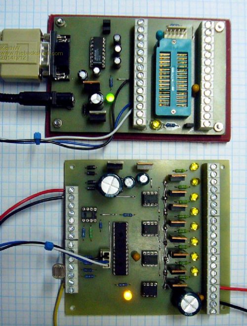
Keith W. |
||||
| WhiteWizzard Guru Joined: 05/04/2013 Location: United KingdomPosts: 2794 |

A very nice application - well done! Would you consider posting a Circuit Diagram as I am sure many people would be interested in this. What was the biggest challenge in completing this nice project? Regards, WhiteWizzard For everything Micromite visit micromite.org Direct Email: whitewizzard@micromite.o |
||||
| vasi Guru Joined: 23/03/2007 Location: RomaniaPosts: 1697 |
I think the description of the project is enough to elaborate al least something similar  . Thanks for posting! . Thanks for posting!Hobbit name: Togo Toadfoot of Frogmorton Elvish name: Mablung Miriel Beyound Arduino Lang |
||||
| Keith W. Senior Member Joined: 09/10/2011 Location: AustraliaPosts: 118 |
Thank you WhiteWizzard and Vasi, I have posted the controller board circuit. It is a screen grab as without my custom library for Diptrace you could not show the circuit, and it does not export as a PDF. Hope it is legible enough. The numerous little Jxx�s on the circuit are the holes and pins for the jumper wires. My way of using Diptrace. 0.1 uF SMD bypass caps are sprinkled under the board. The most challenging part of the project was finding economic, small but well made and unobtrusive LED lights. Now found some for $A15 each. The electronics and software is fairly easy. With MMBasic just two lines of code create the 36 KHz modulated signal and another two reads the ambient light level. Inevitably components that I buy from Rockby become specials AFTER I have purchased but not in this case. I would not have purchased the MOSFETs at the normal $4.80 each at quantity 10 off. The challenge to come is mounting the lights evenly at a correct height without hitting a wall stud; I will create an accurate drawing of their position. I do have fair access to the other side from under the house. It will take a long time to recoup my expenses by saving electricity, but hey, I enjoy building projects and will cause interest when it is complete. 2014-03-12_235753_SLC_Circuit.zip Keith W. |
||||
BobD Guru Joined: 07/12/2011 Location: AustraliaPosts: 935 |
Keith, my windoze 8.1 doesn't like your zip. Bob 
|
||||
| vasi Guru Joined: 23/03/2007 Location: RomaniaPosts: 1697 |
Yeah, file-roller from linux complains also. Is a corrupted archive? Hobbit name: Togo Toadfoot of Frogmorton Elvish name: Mablung Miriel Beyound Arduino Lang |
||||
| paceman Guru Joined: 07/10/2011 Location: AustraliaPosts: 1328 |
That's really neat Keith - pity I don't have any stairs to put it on! I saw that Rockby MOSFET special on their weekly list and wondered if I could use them - should have done it. Greg |
||||
| vasi Guru Joined: 23/03/2007 Location: RomaniaPosts: 1697 |
Solved the problem! In fact is a RAR archive renamed as a zip one... Hobbit name: Togo Toadfoot of Frogmorton Elvish name: Mablung Miriel Beyound Arduino Lang |
||||
| Keith W. Senior Member Joined: 09/10/2011 Location: AustraliaPosts: 118 |

I am sorry about the non true .zip file. Thebackshed would not accept the .png image and I feared that creating a .jpg would remove some legibility but RAR had taken over my ZIP file extensions and I could not seem to create a true .zip. Renaming a .rar file to .zip could still be read (by RAR) and so I fell into a trap. I hope that I have removed RAR�s dominance and that the file attached is actually a true .zip of a .png file. 2014-03-13_101741_SLC_Circuit.zip I almost cannot believe my measurements. Testing the 10 LED lights bought show that they draw less than 7.5 milliamps each at 12 volts DC. They are clearly labeled as �0.6 WATT� but are drawing below 0.1 watt. They are quite bright enough with 3 off 5mm LEDS each. They are not polarity conscious and at the shop were used with an AC supply. I have used two meters and measured a 1K ohm 1% resistor as correctly drawing nearly 12 milliamps to convince myself that they draw just 7.5 milliamps. Wow! My 40 amp capable BUK 9535 100A MOSFETS could certainly be smaller. A benefit of these devices is a logic level gate voltage requirement (5 volts to the gate for 40 amps) and the price at the time. When I make a second card for another project I will fit smaller devices and swap the card. Or as the TC426CPA Drivers will work at higher than 12 volt supply they can drive the lights directly. It will be interesting to log the total illumination time for my project. Likely it will be just a few 10s of hours per year? Keith W. |
||||
| Keith W. Senior Member Joined: 09/10/2011 Location: AustraliaPosts: 118 |
Good progress and nearly time for a new project. Perhaps not finished until Geoff releases the official Micromite version. The project is installed and functioning. Two power transformers of the same type are used, for Light Supply and Controller. The Controller transformer is not optimum for power consumption but limited by availability. With taps for the voltages required I have 12 Volts D.C. un-regulated for Lights and 10.4 Volts D.C. regulated to 5 Volts and 3.3 Volts for the controller and sensors. When all lights are off a solid state relay removes power from the Light Supply Transformer; just enough current is drawn to hold on this relay (Jaycar SY-4080). Having previously mocked up an infrared barrier detector I rashly stated that it would be an easy project, however I had problems with the detectors. I wanted to use a reflective type barrier mounted only on one side for easy installation but found that enough infrared light could be reflected from a person in the beam to prevent reliable detection. Trying to adjust the infrared level to discriminate was unsatisfactory. The infrared receiver model initially tried did not always register that the barrier was now clear although there was sufficient illumination. It could be corrected by breaking the beam again. Changing to a different model, ZD1952 $6.95 vs. ZD1953 $2.25 both from Jaycar, solved this quirk. I now have the infrared LED and the detector on opposite sides and working very well with less than 15 milliamps peak infrared LED current total for both emitters (fed in parallel). The average current is about one quarter of this due to the now 37.8 KHz carrier and 840 Hz modulation. The frequencies were chosen for the ZD1952/RPM7138 detector, one frequency a multiple of the other to aid testing. 
A photo shows the controller and transformers fitted in the case. The controller is mounted below a wide step located where the staircase turns near the bottom. I had cables already with connectors fitted that have a coax bundled with 4 light wires and of the correct length for the detectors. The coax is used for the LED current to prevent this signal from possibly leaking into the detector through its cable. A Detector Circuit diagram is here. 2014-04-01_010755_DipTrace_Schematic_-_INFRARED_BARRIER_Dete ctor.pdf The NE555 pin 7 �Discharge� (open collector transistor) interfaces well to a 3.3V Micromite input c/w a pull up resistor. The 555 acts as a voltage level detector / driver with hysteresis, monitoring the voltage across an R C discharge circuit pumped high continuously (when receiving ) by the (PNP) inverted pulses from the infrared receiver. Constructing SMD printed boards would enable the detectors to be much smaller than the present matrix board construction. 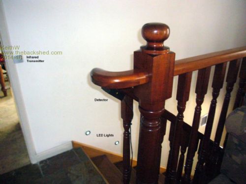
The second photo shows the top of the staircase with the infrared transmitter LED, the back of the detector box below the stair rail and the first LED wall lights. The photo is not erect but shows what is there. The graph shows Controller current vs. CPU clock speed including the drivers and infrared detectors and emitters. The LED Light Transformer current is zero when the solid state relay is off. The Micromite normally runs at 10 MHz equating to 63 milliamps @ 10.5 volts DC = 0.66 Watt. Allowing 1 watt gives 8.7 KWH PA. @ my 28c KWH peak = $2.43 PA for energy. 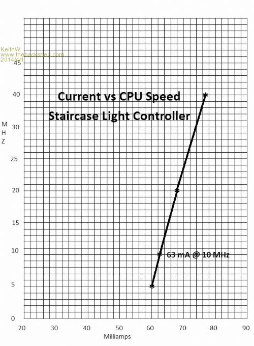
Interestingly the LED power indicator measures to be drawing 13 milliamps through its resistor, about 20 % of the load and the detectors another 20 %. The transformer losses swamp this; the 15VA rated transformer is (just) warm with less than 1 watt load. A power meter indicates 3.4 Watts from the 240 volts or $8.33 PA. In the distant past I could have wound a transformer with less loss. Perhaps a tiny 5 volt switching supply is required? Without improving the power supply loss other tweaking to lower the consumption is not worth the effort. Keith W. |
||||
| WhiteWizzard Guru Joined: 05/04/2013 Location: United KingdomPosts: 2794 |
Keith, This is really good stuff.
Can I suggest one thing. Make a video of it working - and do it in near darkness. Then post it on YouTube and put a link to it on your thread! This will give you a lot more traffic and hence more publicity for you project. And mentioning 'MicroMite' in your video & associated text links will raise awareness of the almighty MicroMite! Nice work & great project . . . . . WW For everything Micromite visit micromite.org Direct Email: whitewizzard@micromite.o |
||||
