
|
|
Forum Index : Microcontroller and PC projects : WhiteWizzard’s soldering method...
| Page 1 of 3 |
|||||
| Author | Message | ||||
Grogster Admin Group Joined: 31/12/2012 Location: New ZealandPosts: 9068 |
This has generated some interest around the fourms, especially by those of us who purchased his MicroMite module, and all of us are suitably impressed. I start this new thread at WW's suggestion, but he himself will chime in here with the exact details - I am not going to steal his thunder. 
What I AM prepared to say, is that he idea does work, and it works very well. In my very first attempt, I was able to come up with a usable result, although, to be fair - I still need to practise it a bit more, but luckily, I have some breakout boards for the 44-pin QFP I was starting to design a MicroMite on, but then WW and Zonker came up with their excellent designs, so my one was aborted. However, I still had three or four breakout boards, which I thought would be useless, but now I have been able to practise on these, so something of a case of serendipity... 
This image is the first one I soldered up using thin solder, gel-flux and a fine-tipped iron, and a VERY steady hand. It worked OK, but took almost an hour to finish pin-by-pin, being careful not to bridge any connections - NOT a good method in hindsight, and plenty of other members will no doubt mention that it should not have taken that long anyway, but.......... 
OK, that's my hand soldering pin-by-pin old method which - lets be frank here - sucks!  
Next, with PM's from WW, I tried his method on another clean board and chip, and this photo was the result: 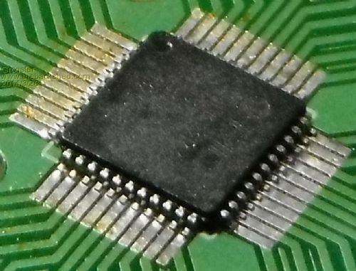
Armed with the right set of tools, this one took about 5 minutes for all four sides of the QFP. The method is dead easy, and seems to work extremely well. I WILL NOT write the specifics of exactly how it is done here, as I believe that is WW's right - he told me how to do it, and it was at his request(in a PM) that I start this thread showing my photos etc, so I am fully expecting that he will fill in the details himself in a post of his own here. But suffice it to say, that having tried the WW way, I am a convert, and will probably NEVER solder SMD chips again any other way then his from this point on. Smoke makes things work. When the smoke gets out, it stops! |
||||
bigmik Guru Joined: 20/06/2011 Location: AustraliaPosts: 2870 |
Gday Groggy, Not knowing exactly WW's method but looking at the result it seems to me to be the SOLDER the entire side and use `solder wick' to suck up the excess solder method. I have used this method and have had reasonable success with it. In fact I used this method to repair Nick's (where are you these days Nick?) CMM for him when he blew up his chip. But you do have to be careful that all joints are soldered as the `solder wick' has the habit of removing ALL solder from the joint. Ideally the joint should have a little `fill' either side of the rear and front of each pin... This is patently missing off many of the pins in your 2nd photo. In fact your first picture may actually be more reliable, if more ugly. If you do use the Solder wick method you MUST check each pin is firmly soldered by a needle (as suggested) or a fine scalpel (as I tend to use) and listen and feel for pins that dont seem the same as the others (It really is noticeable). A perfect joint should look like this picture.. 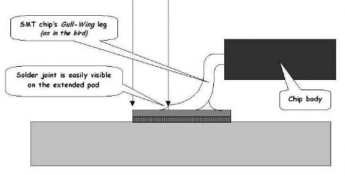
Of course it is all a matter of trial and error and I cant say that I do any better than your efforts either.. Regards, Mick Mick's uMite Stuff can be found >>> HERE (Kindly hosted by Dontronics) <<< |
||||
| Grogster Admin Group Joined: 31/12/2012 Location: New ZealandPosts: 9068 |
Yeah, you are right about the lack of solder - This image WAS my first attempt.
Next time I do one, I will try to leave a little more solder behind. My prototype boards have long footprints, as I had seen a video on YouTube about how if they are long like that, you can apply a tiny bit of solder to each one, then use the iron to "Shunt" the solder up to the QFP pin - might try that. Most QFP footprints DON'T have these extra-long pads though - that was just me stealing the idea from the YT vids. WW has sent me another PM, saying he is busy beta testing at the moment, but will put something here when he gets a chance. Smoke makes things work. When the smoke gets out, it stops! |
||||
| WhiteWizzard Guru Joined: 05/04/2013 Location: United KingdomPosts: 2794 |
Thanks Grogster for starting this new thread. 
I have had many people ask me about how to achieve the neat soldering results seen on the 44-pin MicroMite Modules; some people even doubting that I really am doing it by hand! Well I can guarantee that every 44-pin MicroMite Module out there with you Beta testers has indeed been 'handcrafted'. Soon I will be willing to share with you the method that I am using. What is really nice is that you don't need any expensive tools, and more importantly, if you can solder thru-hole components then I guarantee you that you will easily be able to solder SMDs. This is not a new method (as mentioned by BigMik above) - and is based around the 'solder/flux/wick' method. However, the additional tips that I give (based on experience that has taken several months to perfect) will allow an absolute beginner to create professional looking results on their first attempt. And yes it will take a little practice (but not too much) to leave the ideal amount of solder on the board. If you are doubting these words then please do take a close look at Grogster's photos. The bottom photo is his FIRST attempt using the method along with some of my tips. I have PM'd quite a few BSF members with a rather wordy set of guidance notes. I know this is not the best approach and many of you have suggested I create a video or picture-story-board. I promise I will do something in the very near future but for now I just want to say that I am 100% committed to helping Geoff finish Beta testing the MicroMite software (the magazine deadline is drawing near). So please do drop a post on this thread if you are wanting to learn how to solder SMDs the easy way!
I can then gauge how much genuine interest there is out there. I will post again soon to let you know what items you will need (the strangest is a medium-to-firm toothbrush !?!) . . . For everything Micromite visit micromite.org Direct Email: whitewizzard@micromite.o |
||||
| JohnS Guru Joined: 18/11/2011 Location: United KingdomPosts: 3669 |
I'm interested. I plan not to ever do it, but you never know. John |
||||
Bryan1 Guru Joined: 22/02/2006 Location: AustraliaPosts: 1211 |
Those 44 pin chips turned up today along with more 28 pin chips so I would be very interested in the way you guys are soldering the smd chips. I have done several in the past where I simply wiped some solder flux over the pads then ran some solder over quickly. Then used some solder wick to remove the excess leaving a nice tinned pad. Once I had the chip positioned a quick touch with a small point iron stuck the chip in place then with a bit more solder flux I just soldered all the pins then went over again with solder wick. Below is a pic of a 16F887 on a breakout board, not the prettiest but it works a treat 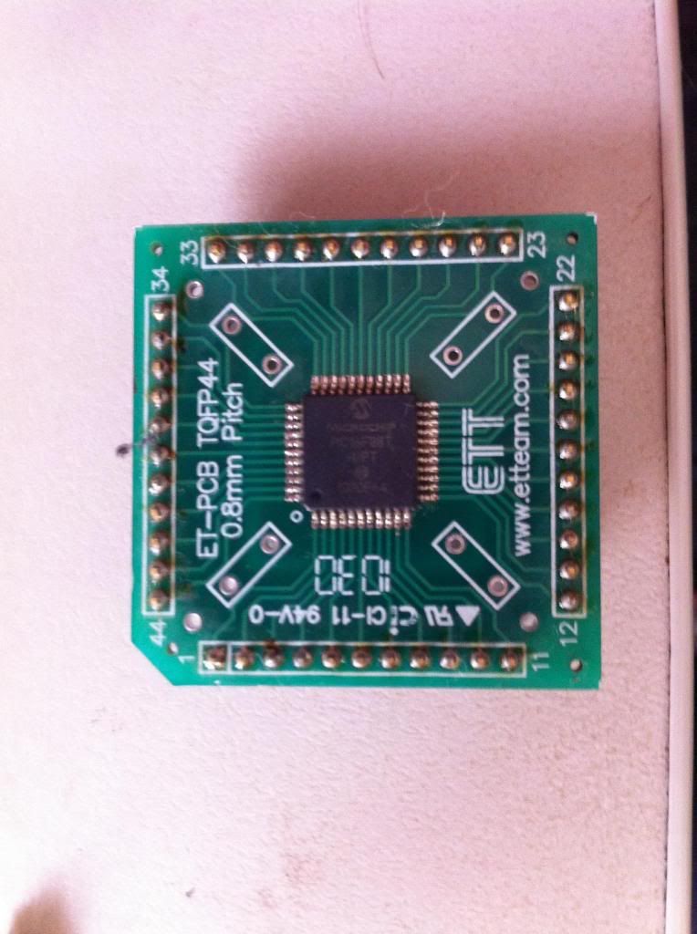 |
||||
| Grogster Admin Group Joined: 31/12/2012 Location: New ZealandPosts: 9068 |
...and here is my second attempt at the WW method - better results this time, as I was able to leave more solder on the pads... 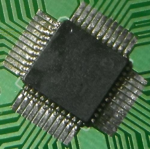
Smoke makes things work. When the smoke gets out, it stops! |
||||
| bigmik Guru Joined: 20/06/2011 Location: AustraliaPosts: 2870 |
Beautiful work Groggy, Now that is definitely good work.. Well Done!! 
Regards, Mick Mick's uMite Stuff can be found >>> HERE (Kindly hosted by Dontronics) <<< |
||||
| Grogster Admin Group Joined: 31/12/2012 Location: New ZealandPosts: 9068 |
Awwwwwwwwww, shucks.......
Thanks, Mick. Smoke makes things work. When the smoke gets out, it stops! |
||||
Lou Senior Member Joined: 01/02/2014 Location: United StatesPosts: 229 |
EEVblog #186 here gives some video on SMT soldering. It was enough for me to get an acceptable 44 pinner soldered down but it doesn't look as good as the WW board, I would like to see the WW method. Thanks, Lou Microcontrollers - the other white meat |
||||
| Grogster Admin Group Joined: 31/12/2012 Location: New ZealandPosts: 9068 |
Yes, that is the exact same vid I have seen, and have been referring to until now. My latest attempt(#2) shown above, is still using the WW method, but just changing one detail in the process, which I won't detail here, until WW has actually listed the process - again, it is not my place to steal his thunder. But I can say that it is 99.9% the same method, and that this one also, only took about five minutes to complete from start to finish... Smoke makes things work. When the smoke gets out, it stops! |
||||
| psergiu Regular Member Joined: 09/02/2013 Location: United StatesPosts: 83 |
I would very much like to learn how to solder SMDs but before that i need some guidance for the right tools. I come from Romania (Eastern Europe) - I learned to solder in the 4th grade, in the school's "practice" classes. Since then, i used the same tool for all my soldering - a 100Watt ~1Kg black bakelite soldering gun with sharpened tips made of cooper wire. Works as a charm for trough-hole - i learned to (somehow) control the temperature by quickly clicking the gun on & off. But i don't think i can use a heavy 100W gun for delicate SMDs. Can anyone recommend me what gun-shaped soldering iron i should get ? (i'm in US now, will order internationally if i can't find-it here). Why gun-shaped ? I tried lots of soldering irons but after almost 30 years of using a gun-shaped tool, i am unable to use a pencil-shaped one. Holding-it by the handle feels like i don't have enough precision so i instinctively try to grab-it closer to the tip ...  
Also what other SMD-friendly materials shall i get ? Right now i'm still using the same leaded solder and chunk of rosin (as flux) i used since last century. Can you guys please help me with some advice on this ? Thanks a lot. |
||||
| PicFan Senior Member Joined: 18/03/2014 Location: AustriaPosts: 133 |
Hello @WhiteWizzard ! Yes, i would like to learn how to solder SMDs the easy way! Please, make a tutorial ! Thank you ! |
||||
| WhiteWizzard Guru Joined: 05/04/2013 Location: United KingdomPosts: 2794 |
Hi PicFan, I will post soon to let everyone know what parts I use (with links) so that you can get prepared. It will be more of a check-list hopefully for most people. Anything that you do require to go and get will be low cost (Don't panic - there's no need for a $399+ temperature controlled solder station here!!). Keep an eye out for my post soon; Please note that I am very busy Beta testing Geoff's MicroMite software at the moment BUT I will get round to it very soon . . . Regards, WW For everything Micromite visit micromite.org Direct Email: whitewizzard@micromite.o |
||||
| Greg Fordyce Senior Member Joined: 16/09/2011 Location: United KingdomPosts: 153 |
Ditto
I can't wait to give this a try and already have some boards ready to be soldered. Greg P.S. will lead free solder work with this technique? |
||||
| Grogster Admin Group Joined: 31/12/2012 Location: New ZealandPosts: 9068 |
Ahhhh - no, you can't.
The recommended power is 15-20W for SMD work. You have to remember that their pins are very small, and too much heat can kill the device. That could be tricky - pretty much ALL soldering irons that can do SMD, are NOT gun shaped, although, I do know the thing you are talking about - I had one here at one point. As for the rosin flux - don't even attempt to solder SMD with that sticky stuff, or any other METAL FLUX - it has to be flux for electronic work. The thing with flux for soldering metals, is that it tends to be acidic, and this will just attack your work. I used to use liquid metal flux for early work, and the board would corrode BADLY after about a week or two. The join worked OK at the time I soldered it, but the flux being acidic, attacked the board, the part, and especially the copper laminate of the board. I WOULD make a list for you, but if you wait just a little, WW will post his method, and included in that, would be a list of what you need. Unfortunately, gun-shaped iron's won't be on that list - sorry. Smoke makes things work. When the smoke gets out, it stops! |
||||
| bigmik Guru Joined: 20/06/2011 Location: AustraliaPosts: 2870 |
Lads, On the subject of soldering Irons... I have bought this one from hobby king Iron And whilst it is very cheap, and I suspected junk quality, I was pleasantly surprised with its quality and usability. So much so my employer went and bought a couple. OK it may not last as long as a weller iron but you cannot complain about the price. Tips are available on ebay for a set of 10 or 12 for about $10 as well. This iron comes with a fine needle (very sharp) point which is good for surface mount, although I would prefer a very fine chisel point to just hold a little solder.. Hobby king has a few varieties of these irons for different countries so make sure you order the correct unit/voltage. Another little trick with hobby king is if you leave the page open for a minute or two it will pop up a special offer (one time only) and a cheaper price by a dollar or two. Hope this is useful to someone out there. Regards, Mick Mick's uMite Stuff can be found >>> HERE (Kindly hosted by Dontronics) <<< |
||||
| WhiteWizzard Guru Joined: 05/04/2013 Location: United KingdomPosts: 2794 |
Unfortunately this method will only work on my 44-pin MicroMite Module PCBs purchased from myself!!
Only kidding.
And yes, lead free solder is ok although I do tend to use the less 'green' solder. The reason being that I bought a job lot some time back and it works very well so never really tried anything else. Grogster. What type of solder did you use? - Please remind me! At least there seems to be some genuine interest out there so that is good to know. Will be in touch again soon . . . For everything Micromite visit micromite.org Direct Email: whitewizzard@micromite.o |
||||
| bigmik Guru Joined: 20/06/2011 Location: AustraliaPosts: 2870 |
Lads, Just my opinion WW, but I would warn newbies away from the lead free solder as in my experience it is more difficult to solder with. Not excessively so, but if you are not very experienced at soldering it would only make the task more difficult. It requires a hotter tip than tin/lead solder. Another annoyance of the lead free solder (they force us to use lead free at work) is that when it dries it is a dull grey colour and I cant help thinking that it is a `dry' joint.. Of course it is environmentally safer and you may be forced due to local rules/laws to use it anyway but if you have a choice get yourself some .5mm tin/lead solder. Regards, Mick Mick's uMite Stuff can be found >>> HERE (Kindly hosted by Dontronics) <<< |
||||
| WhiteWizzard Guru Joined: 05/04/2013 Location: United KingdomPosts: 2794 |
All, While a few of you are asking about irons I think it should be pointed out that I believe a soldering iron is very much a personal thing. What one person loves, another will hate. There are many to choose from out there but when it comes to SMDs I would strongly make a few suggestions to help choose the correct iron: 1> Ensure it is light (or rather, NOT heavy). Using a light iron gives you total control over the iron (rather than the other way round). Likewise, ensure it feels comfortable in your hand - if it feels too big in your hand, it will then be uncomfortable and you will struggle to solder successfully. 2> Do not use a gas iron. A simple mains powered iron is sufficient but suggest somewhere in the region of 18W-25W. It does NOT have to be temperature controlled 3> You do not need a fancy workstation iron with all the bells and whistles. Fine if you have one already then you can use it - but don't go out and get the most expensive workstation around (and some are very expensive) 4> Ensure you get an iron with the ability to change the tip. 5> If there is an option to get a silicone cable then get it. They are so much easier to work with. There are many more things that people love and/or hate about irons; but like I said before, it is very much a personal choice. Just to let you know what I use, I really like this soldering iron, and this tip. The above is just a local supplier to me. Take the part number and look it up on Google to find local suppliers to you. Antex is a reasonably good brand for those who have never heard of them. I will post some other notes like this one with regards to other things required. That way I can drop posts in-between my Beta testing. Please feel free to give feedback on the above, or to ask any further questions . . . For everything Micromite visit micromite.org Direct Email: whitewizzard@micromite.o |
||||
| Page 1 of 3 |
|||||
