
|
|
Forum Index : Microcontroller and PC projects : Simple Servo Test...
| Author | Message | ||||
| Zonker Guru Joined: 18/08/2012 Location: United StatesPosts: 761 |
Evening Gent's.. I got a "HItec HS-55" servo drive unit from my buddy Ed a while back and wanted to start playing with it... I setup the device on the 5v supply coming out of the uMite-28 board and typed in a simple test program... ' servo test p=1.000 Do Servo 2, 50, p Pause 200 p=p + 0.01 Print p If p=>2 Then p=1 Loop I noticed that while running, the servo drive was "lurching" about as it was running thru the code, changing the pulse widths... I thought at first it might be the 5v supply moving around during the position changes... So, after adding a 22uf and .1uf cap to the line, was still acting the same... OK, time to bring out the scope... I was observing the power supply line and the pulse train coming from the prototype board. The power line seemed fine, but, I have noticed that when the servo command is updated, sometimes, the pulse train gets disturbed and creates the wrong pattern on the output line. every time I would see it on the scope, the servo unit (quite correctly) would try to match the waveform pattern. The pulse with is getting corrupted somehow.... I am not sure why... Maybe when you update the pulse width the firmware is trying to "re-init" the hardware and timer channel causing the glitch... Not sure... I thought that maybe my hardware was somehow faulty, so I gave Lou a call to see if he could type it in on a totally different hardware piece and, sure enough, it is happening on his hardware too... I am not sure what's going on here, but I figured that by now, several people would have tested this subsystem already....  Maybe not... Any "servo-heads" out there ...? Maybe I am missing something... Maybe not... Any "servo-heads" out there ...? Maybe I am missing something...
Any feedback on this would be great..!! Thanks in advance Gent's.. 
|
||||
TassyJim Guru Joined: 07/08/2011 Location: AustraliaPosts: 5915 |
I don't have a servo to test with but I did see some strange jitter with the CRO The jitter was not always present but here is one which I was able to capture. 
The middle pulse came in 2 ms early and is 2ms too wide. Here is another example with the oddball pulse coming in very early and staying until it's correct end-time 
I will try and work out when the error occurs. I expect it is when the pulse width gets updated but I hope to confirm this. Jim VK7JH MMedit MMBasic Help |
||||
| TassyJim Guru Joined: 07/08/2011 Location: AustraliaPosts: 5915 |
I changed the program to send a pulse out each loop to act as a trigger for the cro. ' servo test
p=1.000 setpin 24, 8 Do Servo 2, 50, p Pause 200 p=p + 0.01 Print p pulse 24 , 1 If p=>2 Then p=1 Loop The top trace is the PWM and the lower trace is the pulse on pin 24 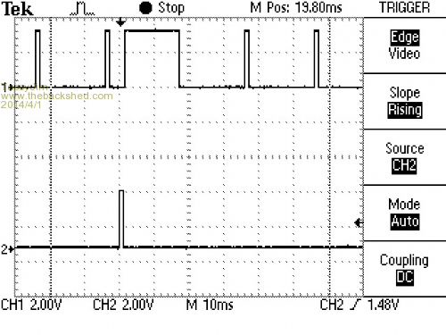
and another: 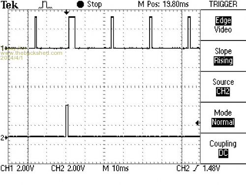
In both cases, the long pulse coincides with the change of pulse width. Jim VK7JH MMedit MMBasic Help |
||||
| Frank N. Furter Guru Joined: 28/05/2012 Location: GermanyPosts: 815 |
Hi, I can confirm this behaviour with my oscilloscope. I think we have a new bug! When you change the p incrementing to 0.1 is the behaviour of our Servo command unusable! The wrong pulses are double so long as programmed! It seems that the first pulse after a PWM change has a wrong timelength... EDIT: The same problem occurs with the PWM command: If you change the line 'Servo 1, 50, p' to 'PWM 1, 50, p' the wrong pulses are over 20x so long as programmed!!! Frank |
||||
| Zonker Guru Joined: 18/08/2012 Location: United StatesPosts: 761 |
Thanks Gents for the conformation..!! It's a good thing we caught this before the firmware goes final. We wouldn't want any "Jerky" robots our there..!! I was actually going to use this subsystem to create gauge displays using the servos as needle drivers for each gauge. the EIS system would collect the engine temp data and send out Rs-485 packets containing the gauge position data for each temp sensor. I was creating this setup for Ed to use with testing the gauge models... Well, let's see what Geoff says about this... Maybe I am not writing the program correctly... |
||||
| Geoffg Guru Joined: 06/06/2011 Location: AustraliaPosts: 3165 |
Thanks folks. I have just got back from a camping trip so give me a couple of days and I will investigate. Geoff Geoff Graham - http://geoffg.net |
||||
| atmega8 Guru Joined: 19/11/2013 Location: GermanyPosts: 712 |
You can also hear this effect if you listen very concentrated ;-) |
||||
| Geoffg Guru Joined: 06/06/2011 Location: AustraliaPosts: 3165 |
Yes, it was a bug and a serious one at that. It was caused by a disagreement between me and the data sheets as to how the PWM duty cycle should be updated (the data sheets won). Thanks very much Zonker, Jim and Frank. I would have hated for that one to go through to the final version. I have sent out Beta 17 with the fix and hopefully that will be the last beta version before the firmware is finalised - which must be in the next week or two because the Silicon Chip issue featuring the Micromite is due on the streets in about three weeks (it is at the printers now). Geoff Geoff Graham - http://geoffg.net |
||||
| Zonker Guru Joined: 18/08/2012 Location: United StatesPosts: 761 |
Thanks Geoff... 
I will try to get the new firmware settled in and tested soon... I also need to update the firmware on the prototype boards in stock and keep things up to date on incoming orders... At the moment, 13 full builds are left for sale... Thanks everyone..!! (MicroMite Rules) |
||||
Lou Senior Member Joined: 01/02/2014 Location: United StatesPosts: 229 |
Geoff, Beta 17 loaded, servo working OK here using Zonker's test code. Pulse looks clean on the scope, looks good to me... Thanks Geoff. Lou Microcontrollers - the other white meat |
||||
| Geoffg Guru Joined: 06/06/2011 Location: AustraliaPosts: 3165 |
Thanks Lou. Geoff Graham - http://geoffg.net |
||||
| Zonker Guru Joined: 18/08/2012 Location: United StatesPosts: 761 |
Confirmed... Beta 17 in the core, and this baby is purrin like a kitten..!! 
Ok... Now to check step granularity... (sweet)... Big tip of the hat goes to Lou on helping me get that damn PICkit-3 thingy going... Turns out, it was crap in the "billy-ware" causing the issue... I will be shooting beta 17 into the remaining Prototype boards for sale... 11 "full builds" left.... Thanks Geoff..!!
EDIT: WOW... I think I can get over 700 steps (discernible) on the servo..! (not totally sure about this yet...) more playtime needed Damn... Time for bed... |
||||
| Frank N. Furter Guru Joined: 28/05/2012 Location: GermanyPosts: 815 |
Thanks Geoff! PWM and SERVO pulses are very, very stable!!! 
I can't see any wrong pulses with my osciloscope!!!
(..now I can plan a little Hexpod with my �Mite! )
Frank |
||||
| paceman Guru Joined: 07/10/2011 Location: AustraliaPosts: 1328 |
It'll be interesting to see what you get there Zonker. Geoff notes in the Manual that most servos have limits from about 0.8mS to about 2.2mS pulse width - I've got three little TowerPro SG90's here that are close to that, 0.6 to 2.4mS. Taking Geoff's limits the full range is 2.0mS and with the 0.005mS accuracy of the pulses, there should be 1/0.005x2 =400 steps. There's no way I can see that many steps on these cheap little SG90's but 400 would be very good. I reckon the re-positioning accuracy of the internal positioning feedback pot and the motor gear backlash will be the limiting factor though unless absolute positioning feedback is used. As I understand it, most "analogue" servers as they call them use an internal potentiometer to balance the voltages. The backlash on those and in the servo gears would be considerably more than should be theoretically achievable with the 0.005mS pulse resolution. There are digital versions of the servos but they're only used in pretty fancy applications and there's still the gear backlash. Greg |
||||
| Zonker Guru Joined: 18/08/2012 Location: United StatesPosts: 761 |
Good morning Greg...! Yep, not exactly sure yet on repeatable position or steps yet, because at the moment, I have no way of testing it by measuring. But, just by listening to the servo settle in after each change, I think I was a bit large with 700 !!... The HS-55 has a little less than 180 degrees of rotation... 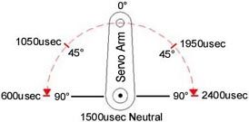
I am still playing around with the numbers... If set to .005usec per step, it seems to get about 350 or so... I was also trying .002usec per step to get the 700... ' servo test 2 p=0.63 s=1 Print "PWM=" p " usec Step=" s Do Servo 2, p Pause 200 If d Then p=p - 0.005: s=s-1 Else p=p + 0.005: s=s+1 EndIf Print "PWM=" p " usec Step=" s If p=>2.34 Then d=1 If p=<0.64 Then d=0 Loop I am still a newbie as this servo stuff and still need more play time...
|
||||
| paceman Guru Joined: 07/10/2011 Location: AustraliaPosts: 1328 |
Hi Zonker, Well if you're getting 350 I'd say that's pretty good. The SG90's do a bit better than 180o - like maybe 200o or so but the accuracy probably isn't great. I believe the pots used in the servos aren't always very linear either so the physical servo centre point isn't necessarily at the mid pulse-width and often they buzz (hunt) at certain locations. I found if they're driven past the end points that can change the re-positioning point too so that's another thing to watch. I'm in Sydney with the kids (35yr. olds ) at the moment and won't be back home (Melbourne) till end of Easter so I can't test anything at the moment. Mind you how you test accuracy and backlash I'm not sure. Maybe super-glue a little shard of mirror to the front of the shaft at an angle to the shaft axis and then focus a light beam onto it from the front. That way you could expand the range pretty dramatically by putting a sheet of paper in front of the shaft and noting where the relection is on the paper. I've never tried this but it might work.
Greg |
||||
