
|
|
Forum Index : Microcontroller and PC projects : Did I kill it?
| Page 1 of 2 |
|||||
| Author | Message | ||||
Grogster Admin Group Joined: 31/12/2012 Location: New ZealandPosts: 9067 |
I made an opps today. Accidentally connected 13.8v system voltage to pin 5 of a PICAXE 08M2. The datasheet for this device says(on page 321) that maximum voltage on this pin should not be more then supply + 0.3v, so I guess I have killed that pin - correct? It ain't workin' (that pin, I mean. the other pins work, but that one seems very un co-operative now...) EDIT: Yes, I have killed it. That pin, anyway.  Further testing has revealed that I can't get anything at all out of that pin. The other pins are fine. Further testing has revealed that I can't get anything at all out of that pin. The other pins are fine.
A schoolboy mistake, really: hook up the wrong wire to the PSU. I will replace the chip. EDIT: Chip replaced and reprogrammed - and working. Live and learn, so they say, but I already knew NOT to do what I did, so what do you call that? (rhetorical!)  Smoke makes things work. When the smoke gets out, it stops! |
||||
| vasi Guru Joined: 23/03/2007 Location: RomaniaPosts: 1697 |
You know? I have a PIC18F2525 with a burned leg. Because of that, I can't even look at it. Poor thing! I know it was me, but I will make up to it, I promise! I... I will find something useful... maybe a Pickit2 programmer on serial interface? Or maybe something else? Some day for sure! Hobbit name: Togo Toadfoot of Frogmorton Elvish name: Mablung Miriel Beyound Arduino Lang |
||||
| Grogster Admin Group Joined: 31/12/2012 Location: New ZealandPosts: 9067 |
I binned the one I killed, as I don't want that one getting back into my stock which could then cause mary-hell with the next development.  Smoke makes things work. When the smoke gets out, it stops! |
||||
OA47 Guru Joined: 11/04/2012 Location: AustraliaPosts: 911 |
Grogster, I had a little chuckle thinking of your chip that is now "legless" and the connotations of your avatar. GM |
||||
| Grogster Admin Group Joined: 31/12/2012 Location: New ZealandPosts: 9067 |
HA-HA-HA!  
Well, my Aussie cousin from across the sea(with the same name, by the way), you might have something there - metaphorically!
Absolutely beautiful comparison, buddy. 
I try to stay off the sauce, but I actually think better on it then off it. I was totally sober when I made that "Opps" today. Smoke makes things work. When the smoke gets out, it stops! |
||||
bigmik Guru Joined: 20/06/2011 Location: AustraliaPosts: 2870 |
Groggy, All, I will share a story from last century when Don asked me to give a second opinion to a chap who came over with a 5 1/4" floppy drive (In the days that these were about $400 each -bare- NO power supply) and it had a 240V power lead and plug hanging off the end.. Apparently the chap bought it second hand and it had a short piece of blue/Brown/Green-Yellow (standard AUS 240VAC power flex colours) wire hanging off the PCB so he removed the small pieces of wire and added his own and plugged it into the power point. Well you can guess the rest cant you? Needless to say it wasnt repairable.. I think I will share a recent lesson I just learned by the design of a new PCB which I will probably release details of later tonight after I give it another look over before I send it off for manufacture. I wanted to protect the analog inputs of a uMite from the possibility of 12V DC being applied so I naturally designed the input to be ZENER protected (through a 1k Resistor) as shown here (the resistor is not shown), using 3v3 Zeners. 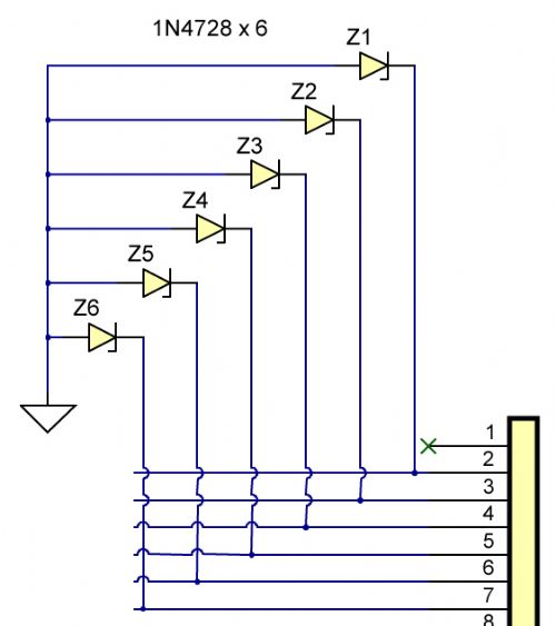
But when I started doing some software tests I was stunned to see that the analog readings were all over the shop.. (OK I understand that close to 3v3 it will taper a bit) but this was WAY out from what I expected from a resistor voltage divider on the input. I scratched my head an eventually cut off the ZENER and shock horror the readings were spot on what I calculated they should have been. I then decided I needed to use 3v6 Zeners to try to get the drop off slope closer to the 3v3 max but this made little difference. What I have finally come up with is this circuit. 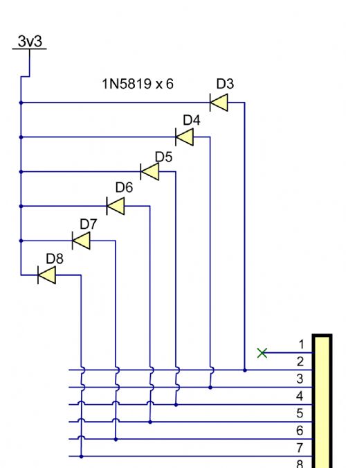
Which works extremely well. The diodes are Schmidt trigger Schotky types and they are fast acting and low forward voltage drop. The expected readings were totally unaffected by the presence of the diodes, so I was happy with that. I crossed my fingers and applied 5V to the 1k resistor (simulating an overvoltage situation) and was very pleased to see the voltage at the input was around 3.46V (Actual power supply gives 3.29v).. Yippee it worked.. Now for the big test I applied 12vDC and crossed my fingers and lo and behold it worked perfectly, the voltage at the analog input pin was clipped at 3.57V just under 0.3v higher than Vcc. Now reading the specs of the chip it states that the operating voltage can be as high as 3.6v so I am happy that it is unlikely to blow the input pin, although the specs state the max input voltage should be Vcc. But I figure that this is protecting against a situation that `should NOT' happen unless someone mis-wires to the device and is probably the best I can do given the circumstances. Sorry for the long winded post but I think this could be educational to others thinking of the same idea. Regards, Mick Mick's uMite Stuff can be found >>> HERE (Kindly hosted by Dontronics) <<< |
||||
| Grogster Admin Group Joined: 31/12/2012 Location: New ZealandPosts: 9067 |
I thought of diodes similar to this concept, but I must be lacking in understanding a little, cos using your image above, if you apply 12v to an input, does this not go roaring through the diode to the 3v3 rail, putting 12v on your 3v3 supply, and blow EVERYTHING connected to the 3v3 rail, and not just the single input pin? I am guessing I am missing something here... I would have thought the first image with the zeners and load resistors to deck would have been the way to go, as you yourself did initially. Smoke makes things work. When the smoke gets out, it stops! |
||||
| bigmik Guru Joined: 20/06/2011 Location: AustraliaPosts: 2870 |
Hi Groggy, As I said, probably missed in the war & Peace that I wrote, they are fed via a 1k resistor as shown in this slightly larger view of the circuit. 
Regards, Mick EDIT*** Going through the 1k it would only allow (12-3.3)/1000 or roughly 8-9ma max current flow. P.S. The bottom line is it works. Mick Mick's uMite Stuff can be found >>> HERE (Kindly hosted by Dontronics) <<< |
||||
| Grogster Admin Group Joined: 31/12/2012 Location: New ZealandPosts: 9067 |
I was not questioning your design, Mick. 
Sorry if it read like that. I was just trying to understand it, and my thoughts were that putting 12v via diodes back into the 3v3 rail - would that not kill anything else on that rail? I guess if there is only 8-9mA current flow, perhaps the voltage is not as critical as I think it is, provided you can prevent any sizeable current flow at that voltage... Smoke makes things work. When the smoke gets out, it stops! |
||||
| bigmik Guru Joined: 20/06/2011 Location: AustraliaPosts: 2870 |
Grogs, I didn't think you did criticise my design, .. in fact this is NOT my design it is standard practice in the industry for protection of Analog inputs, Yes I Googled it, it is widely used. I gather that the reason it works is the current is limited and in comparison to the reserve in the supply capacity it is deemed negligible. The supply voltage was unchanged, actually went up from 3.29v to 3.30v, so it did the trick. I have used ZENERs in the past but always on digital inputs so I didnt think twice to use them on analog but the results were `mind opening'. I learned something in the process and thought I would share as I am certain it would surprise many others out there. Mick Mick's uMite Stuff can be found >>> HERE (Kindly hosted by Dontronics) <<< |
||||
| Goeytex Regular Member Joined: 12/05/2014 Location: United StatesPosts: 74 |
Grog, The circuit may make more sense to you if drawn differently. It is a simple diode clamp circuit that you have likely seen many times. The diode does not conduct current until the voltage approaches Vdd. The higher the voltage the more the diode conducts, keeping the voltage at the PIC I/O pin at no greater than Vdd + .2V (I added D2 which also adds protection again voltages below ground.) Note that the PIC already has internal protection (ESD) diodes on all digital capable Pins except MCLR. The External Diode(s) offer more protection. 
|
||||
| bigmik Guru Joined: 20/06/2011 Location: AustraliaPosts: 2870 |
Hi Goeytex, Grog, others, I omitted the Diode to Gnd (D2 in the above schem) in my circuit as there `shouldn't' be any possibility of a NEGATIVE voltage being applied, but there was a reasonable possibility of 12V being applied.. It was when I tested the circuit and found that it did the job and did the job very well that I decided to post it for all to use in their designs.. I probably should have taken the time to draw a better circuit rather than cut out segments of my one. My main point was that Zener diodes were totally unsuitable for protection of an analog input. Regards, Mick Mick's uMite Stuff can be found >>> HERE (Kindly hosted by Dontronics) <<< |
||||
| Goeytex Regular Member Joined: 12/05/2014 Location: United StatesPosts: 74 |
Hi Mick, My inclusion of the second diode was not to suggest an error on your part, just that it could be included if desired to offer added protection. In the majority of cases the internal ESD diode will handle negative transients as long as the series resistor is included. |
||||
| OA47 Guru Joined: 11/04/2012 Location: AustraliaPosts: 911 |
Thanks Mick, you have saved some development work for me, I too was relying on series resistors and 3v3 zeners on the analog inputs but will go with your suggestions. Keep up the good posts. GM |
||||
| OA47 Guru Joined: 11/04/2012 Location: AustraliaPosts: 911 |
Mick & other interested TBSers I did some quick testing with overvoltage protection on the micromite. Set a PWM output into a diode and 100n cap to generate a variable voltage and then read it via a 1k resistor on an analog input with no overvoltage protection, 3V3 zener to ground and 1N5819 to +3V3. Here is the code: SetPin 26,dout
SetPin 24,ain Pause 100 For f=20 To 1000 Step 10 Print f;","; PWM 2,f,50 Pause 1000 Print Pin(24) If Pin(24)>2.99 Then End Pause 200 PWM 2,stop Next f Here are the results: 
As you can see both types of overvoltage protection alter the way hat the analog inputs see the voltage. Any thoughts? GM |
||||
| bigmik Guru Joined: 20/06/2011 Location: AustraliaPosts: 2870 |
Hi Graeme, That is very interesting... I wonder if it is something to do with the PWM.. As it is really a bunch of 3v3 pulses and not really a stable voltage, a 100nf cap is not a great smoothing device.. I think it might look a lot better with a larger (try 1uf) cap... This is all a learning exercise for me but my tests, which were for my MuP-Security project showed NO difference between the readings of resistor divider networks (I set up a 1/3, 2/3 and 3/3 using 3 x 4k7 resistors... in all scenarios the reading was within .01v of my calculations which is in the range of `didn't matter to me' and `from memory' all the readings were the same with and without the 1N5819's but then I wasn't looking for 0.01v differences. Try a larger cap and see what the differences are.. Regards, Mick Mick's uMite Stuff can be found >>> HERE (Kindly hosted by Dontronics) <<< |
||||
| OA47 Guru Joined: 11/04/2012 Location: AustraliaPosts: 911 |
Mick, I hear what your saying but the green curve which is smooth is using the same diode and cap. |
||||
| bigmik Guru Joined: 20/06/2011 Location: AustraliaPosts: 2870 |
Graeme, Just conjecture on my part but what I suspect could be happening is a crude form of a diode voltage doubling circuit see This link ... Using diodes and capacitors It is possible to multiply the ac voltage many times.. Now we are not seeing a voltage double but it could be doing some thing similar.... I would like to see your results without your dioade and a resistor instead say 1k for a start.. Mick. PS. It obviously shows that the protection diodes CAN have some effect on the analog input.. I dont think you would see that problem with clean analog signals.. An interesting conundrum M. Mick's uMite Stuff can be found >>> HERE (Kindly hosted by Dontronics) <<< |
||||
| OA47 Guru Joined: 11/04/2012 Location: AustraliaPosts: 911 |
Mick and others, To avoid the diode doubling issue, I did the test by stepping a variable power supply and the results are in line with Micks findings and recommendations. 
Thankyou for clearing up my confusion. GM |
||||
TassyJim Guru Joined: 07/08/2011 Location: AustraliaPosts: 5915 |
Are you sure you have the Zener the right way around? The red trace looks like the forward voltage drop. Jim VK7JH MMedit MMBasic Help |
||||
| Page 1 of 2 |
|||||
