
|
|
Forum Index : Microcontroller and PC projects : Did I kill it?
| Author | Message | ||||
OA47 Guru Joined: 11/04/2012 Location: AustraliaPosts: 911 |
Jim you are probably right. You must be more awake than me. I didn't take that much notice of the zener graph as the other one was the important one. I will re-check and re-post if that is the case. GM EDIT: The other problem I have is actually reading the numbers on those little glass buggers. Without very close inspection a 914 could also end up there.  |
||||
bigmik Guru Joined: 20/06/2011 Location: AustraliaPosts: 2870 |
Hi Graeme, All, Unfortunately TBS forum compresses most images to an extent they are often times near uselsss, I can't quite read your last graph, Is the bluish line Just the 1N5819 or is it overlapping the No-Diode as well? Yes I agree with Jim, You probably have the Zener forward biased as it stopped suddenly around 0.6V you have to reverse bias the Zener and I am fairly certain your first graph had it reverse biased. I would love a large clear pic of the 3 tests (maybe zip them up) if possible.. Also as you can see in your first graph (with the Zener reverse biased) that it is absolutely horrible for ANALOG inputs which is what left me Gob-Smacked when I discovered it in my testing.. Your (1st) graph shows it starting to break down (the Zener effect) at around 0.6V and tapering off well before its supposed zener rating.. Regards, Mick Mick's uMite Stuff can be found >>> HERE (Kindly hosted by Dontronics) <<< |
||||
TassyJim Guru Joined: 07/08/2011 Location: AustraliaPosts: 5915 |
I have discovered two things. 1. I need a variable supply that can swing to + and - 5V or so. 2. The 100 3.3V Zeners I bought a while ago are useless. They don't have any clear knee in their breakdown curve no matter what I throw at them. (B.... Ebay) Problem 1 will make an interesting micromite project. Problem 2 is always a risk. Jim VK7JH MMedit MMBasic Help |
||||
| OA47 Guru Joined: 11/04/2012 Location: AustraliaPosts: 911 |
Here is the graphs again with the zener correctly orientated. 
I have included a zip file of the graphs for closer inspection: 
2014-08-24_024016_protected_input.zip GM |
||||
| bigmik Guru Joined: 20/06/2011 Location: AustraliaPosts: 2870 |
Graeme, Those slopes look nice.. The 1N5819 looks to be doing its job beautifully.. The Zener slope is sort of what I saw .. I too bought 100 cheapo Chinese 3v3 Zeners and thought that was it but I then went about bought some 1N4729 3v6 Zeners from Jaycar and they reflected very similar voltages to the cheap Chinese units even though they were 0.3V higher.. I had expected reads of 1.1V (actual read was about 0.8v) , 2.2V (about 1.6v) and 3.3V (2.1v) The problem is not so much the zener being cheap and nasty it is that they start to conduct fairly early, this draws some current even if its small the current goes through the `current limiting' resistor (I used 1k) and that drops the input voltage.. so it ISNT the Zener that is triggering too early, it is that it starts to conduct then avalanches at the specified rating.. If you were to use a lower value of resistor this would mean less of a slope deviation but then the power rating of the Zener would need to be higher to cater for when it needs to do its job. I hope that makes sense? Dont throw away your zeners.. Mick Mick's uMite Stuff can be found >>> HERE (Kindly hosted by Dontronics) <<< |
||||
| TassyJim Guru Joined: 07/08/2011 Location: AustraliaPosts: 5915 |
I couldn't let it go so back to basics for me. The 1N4728 3.3V Zener needs a high current through it before it does it's zener thing so they wouldn't be much use with the high impedance's we are usually playing with. That is why a small signal diode to V+ then a 1k or so resistor to input is a better alternative. This is a chart of current v's voltage drop: There is no way we will want to play with those currents just for measuring. 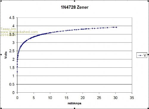
and in a zip so it can be seen: 2014-08-24_031805_zener.zip I knew all of this years ago. The grey matter is slipping.... My 100 Zeners are not faulty, just no use for this application! Jim VK7JH MMedit MMBasic Help |
||||
