
|
|
Forum Index : Microcontroller and PC projects : I2C commands for MCP4725 ?
| Author | Message | ||||
| Zonker Guru Joined: 18/08/2012 Location: United StatesPosts: 761 |
Good evening all..! I am trying to get some test code working for the DAC chip on the LCD 44 pinner board but being an I2C dummy, can't seem to get the I2C commands setup correctly..! All I need is a subroutine to pass the DAC value to (0-4096) and adjust the output pin to the new value.. I am not understanding how to properly send the device address and the rest of the DAC register bits. Any help with this would be awesome..!! (not much hair left) I tried to upload the zipped PDF file but is to large.. Thanks Gent's..! |
||||
Grogster Admin Group Joined: 31/12/2012 Location: New ZealandPosts: 9067 |
I have not done that much with I2C either, but I would expect that: 1) Open the I2C port with the command I2C OPEN 100,100 2) Send bytes to the slave device with the command I2C WRITE addr,opt,data,data,data... 'addr' is the slave address, which is normally specified in this command as a hex byte, but I am pretty sure you can also use binary such as &B1010101 kind of thing - I seem to remember testing that out a while back. 'option' is normally 1, if this is the master on the bus. Plenty of people use the I2C, so it can't be that difficult. 
MOBI is our resident I2C expert, and he has helped me with learning the basics of I2C, so perhaps he will chime in here among others... EDIT: ASSUMING that the DAC slave address was decimal 10, then you could send data to the device with: I2C WRITE &H0A,1,4096,4096,4096 - that would send three bytes of value 4096 to the I2C device at address 10 - 0A hex. All this is untested - I am just going by the manual, and the little I know about I2C - others will have suggestions to add, no doubt. Smoke makes things work. When the smoke gets out, it stops! |
||||
| Zonker Guru Joined: 18/08/2012 Location: United StatesPosts: 761 |
Yep... I think you got it... I was using the 0 option with the command thinking that it was OK to send the stop condition after the command packet... I changed it to a 1 and I think it's doing something... The DAC went to 0 volts... Hummm.. Ok, more playtime needed... I am still a bit confused about the proper location of all the bit positions... 
Thanks Gent's |
||||
| Grogster Admin Group Joined: 31/12/2012 Location: New ZealandPosts: 9067 |
Generally speaking, the master will hold onto the bus(option 1). I guess that is if you have well defined master and slaves, but there would be a need to have the "Master" drop the bus once it is finished with it, if you have a multi-master I2C arrangement. I have never done that, but in that case, one master would have to surrender the bus before another master could take control of it - I think. As I say, that is only in my head at the moment, but is how I think multi-master situations work. Others will put me right or wrong on this in due course, and I may learn something new myself! Smoke makes things work. When the smoke gets out, it stops! |
||||
| Zonker Guru Joined: 18/08/2012 Location: United StatesPosts: 761 |
Yep.... I think this seems to be working... Sub dac_update DAC_HB=DAC_VAL \ 256 DAC_LB=DAC_VAL And &B000011111111 I2C open 100,100 I2C write &H60, 1, 2, DAC_HB, DAC_LB I2C close End Sub wow.. like you said, not that hard... Yikes... I think I am a little less of a dumbass now... (maybe)... |
||||
| Grogster Admin Group Joined: 31/12/2012 Location: New ZealandPosts: 9067 |
Well done. 
Sounds like you were 99% right anyway - it was just that option 0 instead of option 1 seemed to be putting you on the wrong track. I must do some more I2C stuff myself, as I am only a beginner with that stuff myself... Smoke makes things work. When the smoke gets out, it stops! |
||||
TassyJim Guru Joined: 07/08/2011 Location: AustraliaPosts: 5915 |
You beat me to it. I had a MCP4725 but had to wire it up to test. '*** I2C MCP4725 ***
MCP4725_addr = &B1100010 ' MCP4725 address with A0 = 0, A1 = 1 A2 = 0 ' A0 is set by the enduser, A1 and A2 are factory set I2C open 100, 1000 ' Enable I2C do for n = 0 to 4095 step 10 hibyte=n \ 256 lobyte=n mod 256 print hibyte, lobyte I2C write MCP4725_addr, 0, 2, hibyte,lobyte Pause 5000 next n loop A VERY slow ramp with the 5000mS delay. The data sheet is typically confusing. 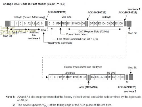
The 'fast mode' is the simplest to start with and PD1/PD0 can stay at zero. That should keep most of us happy. You do need to know how the address bits were set in the factory. In my case A1 is set and A2 is zero. Trial and error will sort it out if needed. @Grogster, We are sending bytes with I2C so 255 is the maximum you can send. Jim VK7JH MMedit MMBasic Help |
||||
| Grogster Admin Group Joined: 31/12/2012 Location: New ZealandPosts: 9067 |
I forgot that I2C is an 8-bit bus, so 255 maximum byte value, yes. My mistake.  Smoke makes things work. When the smoke gets out, it stops! |
||||
| Zonker Guru Joined: 18/08/2012 Location: United StatesPosts: 761 |
Humm... I re-tried using the I2C option set to 0 again, and it seems to still be working ok... Not sure why it wasn't before... Anyway, the DAC chip comes with the EEprom DAC value set to mid-scale. I want to update the stored start-up value to 0, so I need to figure out that one next... Also, if I want to read back the DAC value, then is it correct to use address &H61 instead of &H60 as the last bit controls the read/write function of the IC..? Thanks for the feedback Gent's..! |
||||
| Zonker Guru Joined: 18/08/2012 Location: United StatesPosts: 761 |
Ok... So the test code for the LCDuMite board so far... dir = 1 ' count up Pin(11)=1 ' set backlight ON SetPin 11, dout RTC gettime LCD init 38,37,36,35,12,13 ' setup LCD LCD 1, 1, "LCDuMite Testing" LCD 2, 1, "Program v1.0" Pause 2000 LCD clear LCD 1, 1, Date$ SetTick 1000, dis_update, 1 ' timer 1 SetTick 100, move_dac, 2 ' timer 2 Do Loop Sub move_dac If DIR = 1 Then DAC_VAL = DAC_VAL+1 If DIR = 0 Then DAC_VAL = DAC_VAL-1 If DAC_VAL =< 1 Then DIR = 1 If DAC_VAL => 4095 Then DIR = 0 dac_update LCD 1, 12, Str$(DAC_VAL,4) Print "DAC "; DAC_VAL End Sub Sub dac_update DAC_HB=DAC_VAL \ 256 DAC_LB=DAC_VAL Mod 256 I2C open 400,100 I2C write &H60, 0, 2, DAC_HB, DAC_LB I2C close End Sub Sub dis_update temp$=Str$(DS18B20(19),1,2) Print "Temp "; temp$ Print "Time "; Time$ LCD 2, 1, Time$ LCD 2, 10, Temp$ LCD 2, 15, Chr$(223) LCD 2, 16, "C" End Sub I will try more things tomorrow after church... I think this I2C stuff works awesome..! Lots of different kinds of parts to play around with... |
||||
| TassyJim Guru Joined: 07/08/2011 Location: AustraliaPosts: 5915 |
MMBasic does all the read/write bit setting. Just keep the address at &H60 In your case, &H60 is the upper 7 bits. Some datasheets confuse the issue by giving the full 8bit value, in which case you would need to divide by two. If the address given in the datasheet is greater than 7F, you need to divide by two, otherwise leave it as is. I agree, once you have I2C conquered, the fun begins. Unfortunately, the next datasheet you try to decipher will have you tearing you hair out all over again. Jim VK7JH MMedit MMBasic Help |
||||
| Zonker Guru Joined: 18/08/2012 Location: United StatesPosts: 761 |
Good evening Gent's... Added to the DAC code by adding the EEprom store command... Just did some bit shifting and add a control byte to the mix... Will try the DAC read next... Dim dac_buf(5) Sub dac_store If DAC_VAL >= 4096 Then DAC_VAL = 4095 DAC_VAL=DAC_VAL * 16 DAC_HB=DAC_VAL \ 256 DAC_LB=DAC_VAL Mod 256 I2C open 400,100 I2C write &H60, 0, 3,&H60, DAC_HB, DAC_LB I2C close End Sub Sub dac_update If DAC_VAL >= 4096 Then DAC_VAL = 4095 DAC_HB=DAC_VAL \ 256 DAC_LB=DAC_VAL Mod 256 I2C open 400,100 I2C write &H60, 0, 2, DAC_HB, DAC_LB I2C close End Sub Sub dac_read I2C open 400,100 I2C read &H60, 0, 5, dac_buf(0) I2C close DAC_STAT=dac_buf(0): DAC_HB=dac_buf(1): DAC_LB=dac_buf(2)/16 DAC_VAL=DAC_HB*16+DAC_LB End Sub Of the 5 bytes collected on the dac_read sub, I just store the status byte, and update the DAC_VAL with the contents of IC's DAC registers. I don't bother with the EEprom registers... |
||||
