
|
|
Forum Index : Microcontroller and PC projects : 2R2 resistor on the SD card....
| Author | Message | ||||
Grogster Admin Group Joined: 31/12/2012 Location: New ZealandPosts: 9067 |
Hi all. 
What's the purpose of the 2R2 resistor in series with the power to the SD card on the colour maximite - R17 on the schematic? It's such a low value, I am surprised by it's inclusion - why not just directly connect the SD card to the 3v3 rail? Smoke makes things work. When the smoke gets out, it stops! |
||||
| robert.rozee Guru Joined: 31/12/2012 Location: New ZealandPosts: 2292 |
it will limit inrush current to less than a couple of amps. i'm guessing that SD cards may have a ceramic decoupling capacitor or two on board, and when a card is plugged in these represent a dead short for a fraction of a second. rob :-) |
||||
palcal Guru Joined: 12/10/2011 Location: AustraliaPosts: 1805 |
I agree with limiting the inrush current, but the original Maximite did not have this resistor, so maybe it is not critical. Paul. "It is better to be ignorant and ask a stupid question than to be plain Stupid and not ask at all" |
||||
TassyJim Guru Joined: 07/08/2011 Location: AustraliaPosts: 5915 |
There were some problems with reading SD cards and some users found the resistor was required, others managed better without it. Jim VK7JH MMedit MMBasic Help |
||||
| Grogster Admin Group Joined: 31/12/2012 Location: New ZealandPosts: 9067 |
Interesting..... I have included it, as it is on the schematic - best to follow that, but when I saw it there, it was an eyebrow raising moment. Smoke makes things work. When the smoke gets out, it stops! |
||||
| palcal Guru Joined: 12/10/2011 Location: AustraliaPosts: 1805 |
Maybe it's more to do with the voltage, it would be interesting to know what the drop is across the resistor. Paul. "It is better to be ignorant and ask a stupid question than to be plain Stupid and not ask at all" |
||||
bigmik Guru Joined: 20/06/2011 Location: AustraliaPosts: 2870 |
Hi Grogs, I am not sure of the original reason for it but I found that some of my uSD cards would not work in the UBW32-MCC if the 2R2 was there.. shorting it out fixed the problems. Bottom line is it is not needed and I believe it is trying to be over protective and not damage the SD card. Maybe if it was reduced to 1R Mick Mick's uMite Stuff can be found >>> HERE (Kindly hosted by Dontronics) <<< |
||||
| Grogster Admin Group Joined: 31/12/2012 Location: New ZealandPosts: 9067 |
Cool - thanks. I will bypass it then. It's taking a lot longer then I thought to design this board, even with the UBW32 module at the heart of it! Even double-sided, I have been pressed for space more then once. Fortunately, I have been able to work around the problems - so far.  Smoke makes things work. When the smoke gets out, it stops! |
||||
| bigmik Guru Joined: 20/06/2011 Location: AustraliaPosts: 2870 |
Grogster, What extra are you catering for on your board? The UBW32-MCC that Don Sells is pretty small, maybe the extra bits you want could be designed as plugin via the 2 x 26pin headers along one side The 2 headers are along the rear edge next to the VGA connector. 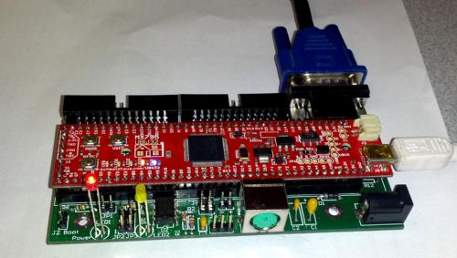
Regards, Mick Mick's uMite Stuff can be found >>> HERE (Kindly hosted by Dontronics) <<< |
||||
| bigmik Guru Joined: 20/06/2011 Location: AustraliaPosts: 2870 |
Damn I hate the way TBS reduces pictures. Here is the same picture ZIPPED up. You can just see R12 under the UBW32 on the RHS and that it is a soldered link (not all of it is visible) Mick 2014-08-19_101515_UBW_plugged_in.zip Mick's uMite Stuff can be found >>> HERE (Kindly hosted by Dontronics) <<< |
||||
| robert.rozee Guru Joined: 31/12/2012 Location: New ZealandPosts: 2292 |
i'd suggest you instead look at replacing the 2r2 resistor with a small inductor - this will still limit the inrush current, while creating less of a voltage drop/droop issue once the 3v3 supply to the card is up. you could also add a small electrolytic capacitor (not tantalum or ceramic) near pin 4 of the card if some cards still do not work. the 2r2 resistor functions in two ways: to protect the card from inrush current, and, to prevent live card insertion causing the maximite to reset or misbehave because of a sudden dropout on the 3v3 rail. just bypassing it may not be prudent. rob :-) |
||||
| Grogster Admin Group Joined: 31/12/2012 Location: New ZealandPosts: 9067 |
Thanks Mick and Rob. I like to be prudent where I can, so will leave it in place. Current PCB size is 200mm x 150mm double-sided. It includes all the basic bits needed for a Maximite by default, such as VGA 15-pin D, sound(via RCA), Keyboard PS/2, SD card holder - all that stuff by default, but also includes all the custom bits I have worked on with the forums' help over the last few years, such as the printer interface with 25-pin D on board, RS232 COM port with 9-pin D on board, provision and circuit for the network module, mains fail detection, COM port switching for remote-access if a network module is installed, on-board connector for the RF receiver module on the roof, all PSU rails for everything on the board and off the board, so that everything is on the one single PCB. This will dramatically cut down the amount of interconnecting wires and sub-boards, to make up a specific system. The UBW32 is at the heart of the system, running MMBASIC. Having discovered iTead Studio's prices, speed and quality of service, I decided to build the mother-ship board, which will do everything I need - I just leave out the bits I don't want depending on features I need, but the board is essentially the same across all installs(save a little bit of programming). I would upload a GIF of the current state of things, but the forums will squeeze the life out of such a big photo. It would be easy enough to link to an external image, then the forums won't squish it - I may well do that.
Smoke makes things work. When the smoke gets out, it stops! |
||||
