
|
|
Forum Index : Microcontroller and PC projects : 40pin DIL Micromite
| Author | Message | ||||
| matherp Guru Joined: 11/12/2012 Location: United KingdomPosts: 8603 |
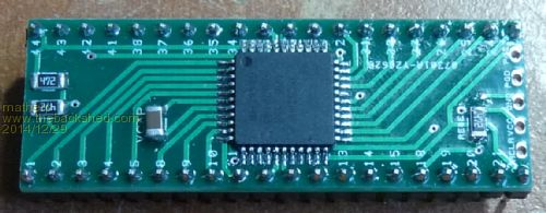
If we assume analog power and analog ground are directly wired to VCC and GND, the 44 pin PIC32MX has 38 discrete pins so I wondered if it was possible to layout a PCB with the form factor of a standard 40-pin DIL chip (0.6" between the rows) to contain the Micromite and key ancilliary components. The difficulty with laying out the TQFP SMD chips on two layer boards is not the width of the tracks but having enough space for vias to get tracks away from the chip in order to switch layers. I've looked up the manufacturing capabilities at Itead Studio and without going right to their limit have managed to get vias small enough to make the layout work. I've also just managed to stay within a 50mm length so that the cost is minimised by using oval pads at the ends. Itead studio allow you to "panel" designs within one of their board sizes so you could get 20 of these boards made for USD9.99 but you then need to cut them up yourself. Alternatively, without panelling you get 10 properly cut for the same price. Together with the PIC32MX, the chip carrier takes: 2 decoupling capacitors on the underside, and on top the Vcap capacitor and RESET and I2C pullup resistors all in 1206 format. It uses standard header strip pins or alternatively turned pins to allow it to be plugged into a standard 40-pin IC socket. In addition there is an ISCP header which can be used to program the PIC. I find that for one-off programming there is no need to solder in the ICSP header pins, just insert the pins and hold them pushed at an angle to get good contact while the PicKit does its work. Let me know if anyone wants the gerbers. 2014-12-13_104558_Adapter_-_PCB.pdf |
||||
| Geoffg Guru Joined: 06/06/2011 Location: AustraliaPosts: 3167 |
Wow, the great PCB designs keep coming. This is neat. Geoff Graham - http://geoffg.net |
||||
| robert.rozee Guru Joined: 31/12/2012 Location: New ZealandPosts: 2294 |
a nice bit of layout. though one thing to be cautious of is sharp corners - the track from the pin labelled "21" to "PGD" is one such example. i've always been told that the inside of corners can present etching problems, as well as traps for etchant. see the below example with 'bad corners' marked in red: 
so i try and keep all angles as shallow as possible. in the past i've done this by making corners two turns of 22.5 degrees wherever possible, and if unavoidable 'knocking off' the sharpness with a little bit of track added in. cheers, rob :-) addendum: just spotted, you have a short between pins 42 and 43, and the routing of pin 33 is unnecessarily complicated. does the package you are using have a 'design rule check' facility? |
||||
| matherp Guru Joined: 11/12/2012 Location: United KingdomPosts: 8603 |
Rob The design is certainly checked and there isn't a short between 42 and 43; what made you suspect that? What looks like a via near pin 44 is just the pin 0 mark on the silk screen. I've got rid of the acute angles, worst case now is 90deg. I've rerouted 33 - thanks Thanks for the input Peter |
||||
| robert.rozee Guru Joined: 31/12/2012 Location: New ZealandPosts: 2294 |
it could just be the way acrobat reader is rendering the PDF file, attached is a zoomed-in view of the area as it displays on my PC: 
cheers, rob :-) |
||||
| Zonker Guru Joined: 18/08/2012 Location: United StatesPosts: 761 |
Awesome Pete... Another plugin... Using these makes doing quick hardware setups easy..! Just drop it onto a vector board and start wiring.... I think we are starting to get a good selection of prototyping motors to use for projects..! |
||||
| matherp Guru Joined: 11/12/2012 Location: United KingdomPosts: 8603 |
Here is a slight update. I've got rid of all the smallest vias and changed the VCC/GND pins so there is now one of each in the middle pair of pins on each side. These are arranged such that the chip can be plugged in either way round and the supply will still be correct. I've attached the gerbers as well as the PDF of the layout. I'm getting a set made by Itead. If anyone wants one of these or any of my PC designs I suggest you try and twist the arms of bigmik, WhiteWizard or equivalent. The designs are completely available for anyone to use or abuse as they wish. The designspark file is also available if anyone wants it. 2014-12-14_110136_Adapter_-_PCB.pdf 2014-12-14_110150_Adapter.zip |
||||
| matherp Guru Joined: 11/12/2012 Location: United KingdomPosts: 8603 |


|
||||
