
|
|
Forum Index : Microcontroller and PC projects : SkinnyMite 1B...
| Page 1 of 2 |
|||||
| Author | Message | ||||
Grogster Admin Group Joined: 31/12/2012 Location: New ZealandPosts: 9063 |
Here is the latest version. This one fixes that  -ing regulator input error, and also the legend on the silkscreen now reflects what the pinout actually is. -ing regulator input error, and also the legend on the silkscreen now reflects what the pinout actually is.
PCB now has a heap more ground vias where-ever I could fit them in, so hopefully this will be enough now. I have added USB+ and USB- header pins to allow for POSSIBLE future expansion into the USB area. Currently, this is not supported, but it may be some time in the future in some way - better to have the pins and not need them, then need them and not have them. 
ALL LAYERS: 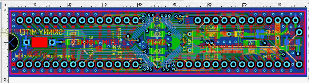
TOP COPPER: 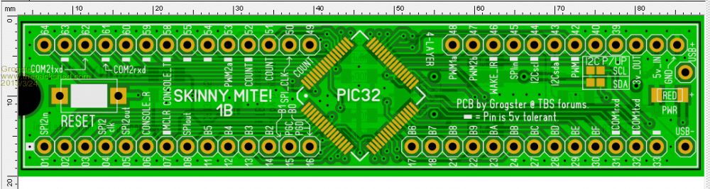
INNER 1: 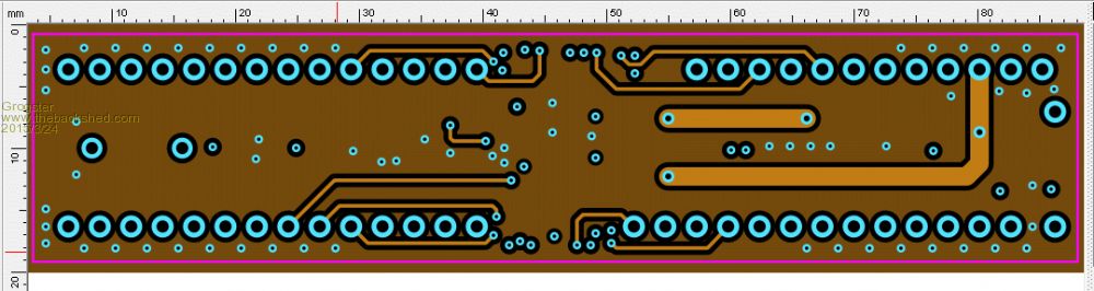
INNER 2: 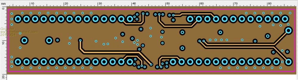
BOTTOM COPPER: 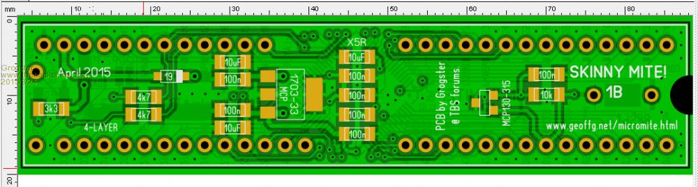
This board will be getting ordered probably next week. If there is any interest from any members, please reply to this thread. EDIT: WHOOPS! The USB pins are not on a breadboard-happy grid. I will look at changing this aspect of things to something else... EDIT: Sod-it. I will leave it as is. USB pins mount from the TOP of the board, and you can plug into them if you ever need to. Smoke makes things work. When the smoke gets out, it stops! |
||||
| MicroBlocks Guru Joined: 12/05/2012 Location: ThailandPosts: 2209 |
Is this by comity.:) :) If so then this is my wish: You could probably fit a mini or micro usb on that side. Bonus is that you can then power it from a usb port. The pins are already there and the 5v and GND pins are very close. Microblocks. Build with logic. |
||||
| WhiteWizzard Guru Joined: 05/04/2013 Location: United KingdomPosts: 2794 |
I'm with TZA on this - useful to have power readily available. Other option is a 5-way header to accept a USB Module (but maybe limited on space to physically squeeze this in!)
WW For everything Micromite visit micromite.org Direct Email: whitewizzard@micromite.o |
||||
| Grogster Admin Group Joined: 31/12/2012 Location: New ZealandPosts: 9063 |
Okey dokey, let me see what I can squeeze in there. You are both correct - it makes more sense to have a USB socket over the pins - good idea, guys. 
I have some Mini-USB connectors, but many people these days seem to have standardized on Micro-USB connectors - is there a logical reason for this? Smoke makes things work. When the smoke gets out, it stops! |
||||
| Grogster Admin Group Joined: 31/12/2012 Location: New ZealandPosts: 9063 |
I have had an email from Geoff explaining that the USB on the 470 will not work without an external crystal oscillator, so it will NEVER be able to be supported on the SkinnyMite without external crystal oscillator(even if people wanted it), and I am not about to try to add that - the SkinnyMite works just fine on the internal oscillator for everything but USB, and USB is not technically supported on the 470 anyway, so..... So, the 1B will not have the USB pins - I will remove them. Smoke makes things work. When the smoke gets out, it stops! |
||||
| WhiteWizzard Guru Joined: 05/04/2013 Location: United KingdomPosts: 2794 |
In the hobbyist world the Mini B seems to have more preference due to its better 'robustness'. The MicroB took off with the mobile phone chargers trying to standardise on things. However, hobbyists generally find the MicroB too 'flimsy'. That said, I do use both connectors, however, I use far more Mini's than I do Micro's. If your PCB 'real estate' is at a premium then you may be better off with the Micro. Lets see what others think!! WW (Building another Skinny 1A as we speak - have to keep remembering that Console Rx is on Pin 6  ) )
For everything Micromite visit micromite.org Direct Email: whitewizzard@micromite.o |
||||
| WhiteWizzard Guru Joined: 05/04/2013 Location: United KingdomPosts: 2794 |
Just seen your last post - would you still consider a 5-way header for attaching a USB Module (for Power and/or for Console)? For everything Micromite visit micromite.org Direct Email: whitewizzard@micromite.o |
||||
| Grogster Admin Group Joined: 31/12/2012 Location: New ZealandPosts: 9063 |
Yes, would still consider header - would need to be small one though. Standard 2.54mm pin headers will not fit. Do you have any suggestions on connector or pin type? EDIT: Looking at it, actually standard 2.54 header WOULD fit, if I moved the LED a little. The header would be on the TOP SIDE, and would not fit the bread-board-friendly footprint. Can you live with that? Smoke makes things work. When the smoke gets out, it stops! |
||||
| WhiteWizzard Guru Joined: 05/04/2013 Location: United KingdomPosts: 2794 |
Definitely go for a header if you can. It does not need to be 'breadboard friendly' in my eyes since its best if you plug the USB module into the Skinny - not the breadboard; hence also topside is perfect. One comment with the Skinny's LED - can you make it an 0805 package (this may help also with space for the header). I find the 1206/1210 LEDs appear unnecessarily 'big' on a small PCB like this - just a suggestion. WW For everything Micromite visit micromite.org Direct Email: whitewizzard@micromite.o |
||||
| Grogster Admin Group Joined: 31/12/2012 Location: New ZealandPosts: 9063 |
OK, I will rustle up a header top-side for this. On the 1206, I use this size, as I have pretty much standardized my SMD passives on that size package. I could get 0805 LED's though - will give it some thought. 1B uses a 3k3 for the LED instead of 1k, as these SMD LED's are very bright despite their small size, so the 1B won't have such a dazzlingly bright red LED when powered up. Smoke makes things work. When the smoke gets out, it stops! |
||||
| Grogster Admin Group Joined: 31/12/2012 Location: New ZealandPosts: 9063 |
Can you please define these pins? Console would be three, so are you meaning that two of the pins would double-up as power pins? 5v-IN, 3v3-OUT, Ground, ConsoleTXD, ConsoleRxD kind of thing? Smoke makes things work. When the smoke gets out, it stops! |
||||
| MicroBlocks Guru Joined: 12/05/2012 Location: ThailandPosts: 2209 |
Consider this option: Remove the cutout, this will allow the reset switch to be placed closer to the edge. You then have room to put in a 5 pin header. From left to right: 1 - RESET 2 - GND 3 - ConsoleRxD 4 - ConsoleTxD 5 - VDD A three pin header spaced a little apart from the 5 pin header: 1 - 5v in (This would go to the input of the regulator) 2 - VDD (this connects to the Vdd on the 5 pin header) 3 - 3.3v in/out (This connects to the output of the regulator) On the right i would place a usb mini connector (Through hole) and connect VDDUSB, D+,D- and GND. You connect the VDDUSB to the input of the regulator. A user can then choose which power source to use. If a console is not necessary then it can be powered directly from the usb port. This will allow the use of cheap telephone charger like power supplies and standard cables. This will keep cable clutter to a minimum. As the USB connector for now is only used to provide power a conflict can occur when the console/power pins are used. The use would be to remove the jumper when USB powered. When no USB is connected then the jumper can be placed between VDD and 5v or VDD and 3.3v. The PIC32MX4xx series can use the internal oscillator for USB! It is less reliable then a external crystal oscillator but for low speeds (like serial) it should be able to work according the datasheet on page 151. Maybe not in the case of MMBasic as many other things are going on at the same time, but other uses might. [code] bit 2 UFRCEN: USB FRC Clock Enable bit (Note 1) 1 = Enable FRC as the clock source for the USB clock source 0 = Use the Primary Oscillator or USB PLL as the USB clock source Note 1: This bit is available on PIC32MX4XX devices only. [/code] If a external oscillator is necessary a small pcb that will piggyback on pins GND, 39 and 40 could be made. I think it will add more ways to use the skinnymite. Microblocks. Build with logic. |
||||
| WhiteWizzard Guru Joined: 05/04/2013 Location: United KingdomPosts: 2794 |
My personal approach would be as follows: 5-way header to attach a USB module/cable. This allows the Skinny to be powered as well as 'programmed' from a computer. The 5-way I have standardised on is as per my USB module: Gnd, MM TxO, MM RxI, 3v3, 5v. If the header is on the left of your board then Gnd nearer the bottom edge. If the header is on the right hand side then Gnd nearer the top edge of the Skinny (this is purely so the USB cable doesn't go 'over' the Skinny but instead comes 'in from the side'). Use the 5v from the header (USB 5v PTC protected) to drive your onboard vReg, and leave the 3v3 header open circuit. Take a look at BigMik's MuP - he uses this exact approach and it works well. As USB is less likely for now on the 470 then I wouldn't bother with a USB socket (even for power). The 5-way header/USB module keeps cable clutter down when developing/programming/testing etc. Then final application will be embedded where you can easily just supply 5v to the pin you already have. I wouldn't bother with a Reset signal on the header since you already have a reset switch for the rare occasion you may need a reset. As stated above - this is my approach on things - not necessarily the correct approach For everything Micromite visit micromite.org Direct Email: whitewizzard@micromite.o |
||||
| Geoffg Guru Joined: 06/06/2011 Location: AustraliaPosts: 3165 |
I do have plans for a USB console on the MX470 but it will require a crystal - the internal RC oscillator is just not stable enough and as a result the USB is too unreliable (I have tried it). Geoff Geoff Graham - http://geoffg.net |
||||
| Grogster Admin Group Joined: 31/12/2012 Location: New ZealandPosts: 9063 |
Thanks for the comments and suggestions fellas. I will have a play with it tomorrow and see what I can rustle up. Smoke makes things work. When the smoke gets out, it stops! |
||||
| matherp Guru Joined: 11/12/2012 Location: United KingdomPosts: 8584 |
Grogster My view FWIW I would stick to the current formula without a USB socket for 1B. As Geoff notes, a crystal is needed to use USB, there should probably also be a few other components (see the Colour Maximite circuit diagram) |
||||
| Grogster Admin Group Joined: 31/12/2012 Location: New ZealandPosts: 9063 |
Yes, current formula will be retained. USB D+ and D- will not be routed out. USB socket of any kind will not be included. I will include the extra header pins for a serial-to-USB module a'la WW's module. That is easy enough to add with the board being 4-layer, and would be handy, as then a module such as WW's one can both power the board, and talk to the console. Smoke makes things work. When the smoke gets out, it stops! |
||||
| Grogster Admin Group Joined: 31/12/2012 Location: New ZealandPosts: 9063 |
WhiteWizzard - is this the module you are referring to? Does it use the same pinout as some other serial modules that can be had? Just trying to make it compatible with multipule USB-serial modules if possible, but that is a big ask! 
At this stage, I will design for your cute little red USB-serial module. If you install a 5-way female header on the top of the board, your little red cutie-pie would plug directly into it..... Smoke makes things work. When the smoke gets out, it stops! |
||||
| WhiteWizzard Guru Joined: 05/04/2013 Location: United KingdomPosts: 2794 |
@Grogster Would you like me to send you a USB module to check everything with?
WW EDIT: Your last post came in after I had just typed this one! YES. Thats the correct module . . . For everything Micromite visit micromite.org Direct Email: whitewizzard@micromite.o |
||||
| Grogster Admin Group Joined: 31/12/2012 Location: New ZealandPosts: 9063 |
OK, thanks for that confirmation. Does your wee module use the same pinout as other modules you can get? Smoke makes things work. When the smoke gets out, it stops! |
||||
| Page 1 of 2 |
|||||
