
|
|
Forum Index : Microcontroller and PC projects : SkinnyMite 1B...
| Author | Message | ||||
| WhiteWizzard Guru Joined: 05/04/2013 Location: United KingdomPosts: 2794 |
@Grogster. There seems to be no 'standardisation' (the debate has been had before!!). I wouldn't try and make it 'Arduino' like; or Cheap Chinese Clone type. Lets stick to what we need, Tx Rx, and power. BigMick put two headers on his MuP, one for my USB module, and one for DonTronics supplied USB cable. The signals are the same - just in different sequence. The way I look at it is that with 'any' console/power header then version 1B will be an improvement (and useful one too) over 1A. No need for a breadboard even, just plug in a USB module and start programming. So shall I ship you one (or do you have one already from the 'early' days?) WW For everything Micromite visit micromite.org Direct Email: whitewizzard@micromite.o |
||||
Grogster Admin Group Joined: 31/12/2012 Location: New ZealandPosts: 9063 |
Very generous - thank you. No, I don't have any of the little USB module. I will design it to fit your module - might as well support other users products in this area, rather then more super-cheap stuff from China - and at least we know that your FTDI chips are genuine.  (lets not go there again!) (lets not go there again!)
Anyone without a WW serial-USB module, can still hook up their own one using the existing pins. Smoke makes things work. When the smoke gets out, it stops! |
||||
BobD Guru Joined: 07/12/2011 Location: AustraliaPosts: 935 |
I was looking on eBay today for usb to serial ttl and most of what I saw was Prolific 2303. All of the fake FTDI seem to have been flushed. |
||||
| Grogster Admin Group Joined: 31/12/2012 Location: New ZealandPosts: 9063 |
Ahhh, but are they GENUINE Prolific 2303's? (rhetorical!) 
There was a whole heap of Prolific clones out there too, and I have had a bad run with those pieces of excrement. Here is the revised PCB: TOP COPPER: 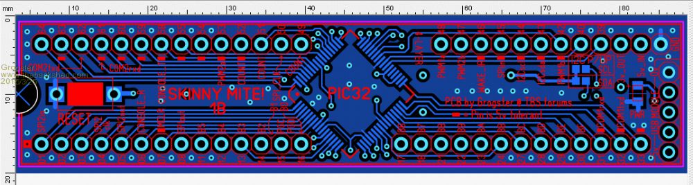
INNER LAYER 1: 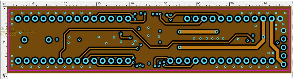
INNER LAYER 2: 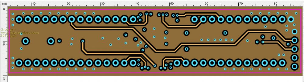
BOTTOM COPPER: 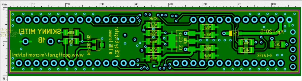
This is designed to directly accept one of WhiteWizzard's USB-serial modules, with the USB cable going away from the SkinnyMite off to the right. WW's USB module could either be plugged in if you used female header strip on the top of the SkinnyMite PCB, or you could permanently solder the WW USB board to the SkinnyMite for a permanent USB connection - albeit with a slightly odd-looking PCB shape if you did it like that permanently. The PCB takes the 5v USB feed from WW's module, but DOES NOT use the 3v3 from WW's USB module, as the SkinnyMite's on-board 3v3 regulator comes out to a pin you can plug into if you need 3v3, and the SkinnyMite regulator can handle more then the 50mA current limit of the WW board 3v3 output. Smoke makes things work. When the smoke gets out, it stops! |
||||
| MicroBlocks Guru Joined: 12/05/2012 Location: ThailandPosts: 2209 |
Unfortunately that will not always work and if i have to make a guess it probably not work with most USB-Serial modules. The decision to put the console RxD to pin 6 makes it a 3.3v only solution. Before the pins were 58 and 59 which were both 5v tolerant. Most usb-serial modules i know have a jumper to choose between 5v and 3.3v. This will then be the voltage used on the VDD pin but more important that will also be the levels used on the TxD and RxD pins. Connecting one of those will certainly kill the PIC32. There are modules that can have different VDD and output levels but they are not that common anymore. To prevent damage from happening i would suggest to not allow 5v to be on that connector. This will then force users to use 3.3v and if they still use 5v then it is their own fault. Another way would be to use a resistor to lower the voltage (and current) to a lower level, that would probably be best and it will make it more robust against wrong voltages levels. Microblocks. Build with logic. |
||||
| WhiteWizzard Guru Joined: 05/04/2013 Location: United KingdomPosts: 2794 |
Out of interest, I decided to build one of my USB modules with a clone FTDI chip (34p I paid) to see what would happen (after all the fiasco a few months back). Well, the module initially worked well (once!) but then Windoze couldn't see it whenever it was plugged in after that. 
Also I noticed it warmed up quite nicely (when it was working)  .The current drawn for the whole module was 59mA; it should be 18.8mA (for genuine FTDI). .The current drawn for the whole module was 59mA; it should be 18.8mA (for genuine FTDI).
Needless to say, it has gone in the bin  For everything Micromite visit micromite.org Direct Email: whitewizzard@micromite.o |
||||
| WhiteWizzard Guru Joined: 05/04/2013 Location: United KingdomPosts: 2794 |
@TZA, Some of the jumper selectable modules are very limited in the current you can 'pull' from them so will not be suitable for powering the Skinny. My module takes the 5v USB signal and is passed through a PTC - perfect for the Skinny. Rather than try meet every USB module configuration, why not simply meet the requirements of the Skinny? It needs 5v in to power it (more than 50mA!!), and needs a console connection. What Grogster has produced will work very well. I do agree about potentially adding a resistor for people who inadvertently connect a 5v signal level from a USB module, but that is the only change needed (I believe the RXD will still work if a 3v3 signal level is used with the series resistor in place). KEEP the 5v in on the header - and simply add a resistor - everyone happy! As no doubt you are aware, it was matherp who swapped to pin 6 for RXD to correct an 'issue' he was experiencing. This is irrelevant with the aforementioned resistor added.
WW For everything Micromite visit micromite.org Direct Email: whitewizzard@micromite.o |
||||
| MicroBlocks Guru Joined: 12/05/2012 Location: ThailandPosts: 2209 |
One remark about the used supervisory chip. You are using a MCP130-315. 
This version has a built in 5k pullup resistor. The 10k resistor that is also a pullup will lower the total resistance to about 3.3K. The MCP120 has no internal pullup. Microblocks. Build with logic. |
||||
| Grogster Admin Group Joined: 31/12/2012 Location: New ZealandPosts: 9063 |
@ TZA - You have a point about the 3v3 vs 5v thing I will ask WW what the FTDI voltages are. While testing my own SkinnyMite here, I used a MAX2323 board powered from 3v3, so that the RXD and TXD were no more then 3v3. You have a very valid point, and thank you for pointing that out. On the MCP130, yes, I chose it over the 120 as it already has the pull-up. Then I decided to add the 10k resistor in case people could not source the 130 at their end of things. I think with the 1B, I will remove the extra 10k pull-up resistor, and if necessary, I can supply the 130 with the PCB's - I have been doing a bit of that with the 1A's anyway..... @ WW - Does your cute red FDTI module use 5v or 3v3 logic at it's TXO and RXI pins? Smoke makes things work. When the smoke gets out, it stops! |
||||
| WhiteWizzard Guru Joined: 05/04/2013 Location: United KingdomPosts: 2794 |
To clarify, my USB module uses 3v3 signal levels (it is based on the FT232RL). Reiterating my previous post: The Rx and Tx connections will work with your current design BUT I would still consider adding in a 1K resistor (in series) on the Skinny's RxD input. This is NOT required for my module BUT is a safety measure in case anyone uses a different module that outputs a 5v signal level. Regarding the 10K resistor on the supervisory chip, why not simply leave the 'pads' in place on your PCB and then make it clear in the instructions to only solder it in if using a MCP120, otherwise, if using a MCP130 then leave the resistor out! WW For everything Micromite visit micromite.org Direct Email: whitewizzard@micromite.o |
||||
| Grogster Admin Group Joined: 31/12/2012 Location: New ZealandPosts: 9063 |
Okey dokey. 10k added back, with silkscreen prompt to only install one or the other. 1k series resistor fitted for console RXD. This is in series with either a USB module for the console, or pin6 of the module as standard. This should suffice, yes? ALL LAYERS: 
Forum software has squeezed this image, so here is a link to a full-size high-res image. Smoke makes things work. When the smoke gets out, it stops! |
||||
| WhiteWizzard Guru Joined: 05/04/2013 Location: United KingdomPosts: 2794 |
 What do you mean by 'either' - is there an option?? What do you mean by 'either' - is there an option??
The four layers being superimposed on each other mean I can't follow the tracks to answer this. . . . sorry  For everything Micromite visit micromite.org Direct Email: whitewizzard@micromite.o |
||||
| Grogster Admin Group Joined: 31/12/2012 Location: New ZealandPosts: 9063 |
It means that the USB module RXD pin on the header(with respect to the SkinnyMite - TXD of your module) is connected in parallel with pin6 of the SkinnyMite, then both of these are routed via a 1k resistor, to the PIC32 for added RXD protection. You can use EITHER the USB module, or the pins of the SkinnyMite for your console, but EITHER one will work. Click the link(if you have not already) to a nice big image you can see. I got lazy, and could not be bothered to crop all four layers and upload each one like I did before! Smoke makes things work. When the smoke gets out, it stops! |
||||
| WhiteWizzard Guru Joined: 05/04/2013 Location: United KingdomPosts: 2794 |
I'm understanding now
Yep that is good. Sorry I haven't posted your USB module yet; I will get around to it tomorrow. Just out of interest, do you have a spare (genuine) FT232RL SMD chip in your component drawers? If so then I can AirMail you several part populated PCBs as a 'letter' (this would be cheaper than a 'small-parcel'). Let me know!! WW For everything Micromite visit micromite.org Direct Email: whitewizzard@micromite.o |
||||
| Grogster Admin Group Joined: 31/12/2012 Location: New ZealandPosts: 9063 |
No, sorry. All I have is those useless Mac-Blue translucent moulded 2303 clone cables - I should biff them. In fact, I think I will - they are not worth the effort. Genuine ones cost more, but they just work - funny that...... I will upload another set of layer images later. That ALL LAYERS image is not really any use with multi-layer, eh? (rhetorical) Smoke makes things work. When the smoke gets out, it stops! |
||||
| Grogster Admin Group Joined: 31/12/2012 Location: New ZealandPosts: 9063 |
UPDATE: OK, this is now the final of this board. Please take a look, and see if there is anything I missed. I have added ground via's wherever I could fit them. I will probably be ordering some of these by the end of the week, unless someone spots something obvious that I have missed...... TOP COPPER: 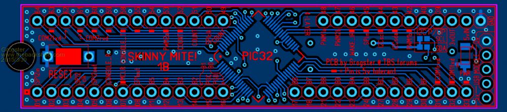
INNER LAYER #1: 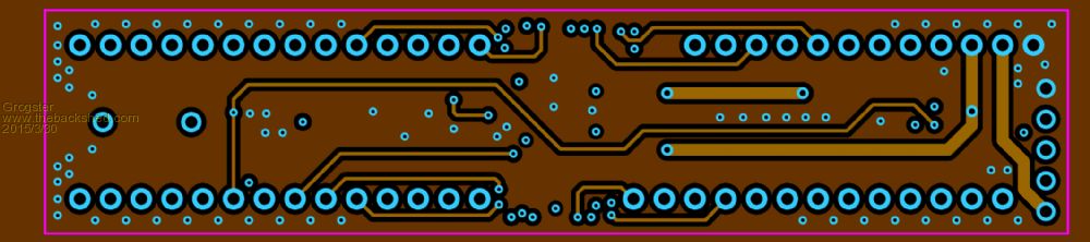
INNER LAYER #2: 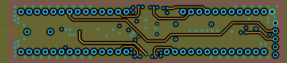
BOTTOM COPPER: 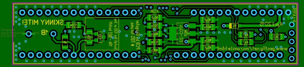
Let me know if anyone spots anything missing. Changes from version 1A: - Regulator input fix - Heaps more grounding via's where-ever I could fit them - 1k in series with the console RXD for 5v protection - Silkscreen updated to matherp's latest pinout - Box around 130 & 10k on bottom to install only one not both - WhiteWizzard USB module holes on the right-side - Main ground point no longer a thermal pad(ditto WW's GND pin) Smoke makes things work. When the smoke gets out, it stops! |
||||
centrex Guru Joined: 13/11/2011 Location: AustraliaPosts: 320 |
Hi Grogster The pin second from the bottom of the the 5 pin header at the right hand end does not appear to be connected to anything?? Or am I missing something as usual. Cliff Cliff |
||||
| Grogster Admin Group Joined: 31/12/2012 Location: New ZealandPosts: 9063 |
Thanks for your comment. 
It's fine - it's WhiteWizzard's USB module header, and that pin is 3v3 out from the module, but WW's USB module does not have the grunt to feed the 470 as the FTDI chip on the WW USB module will only allow you 50mA of current. So, it is just a dummy pad to solder the socket to, but is not connected to anything by design. Thanks for your comment. Smoke makes things work. When the smoke gets out, it stops! |
||||
| Grogster Admin Group Joined: 31/12/2012 Location: New ZealandPosts: 9063 |
The 1B PCB's have arrived, for any of you who are wanting the updated version. Flick me a PM if you do - same price as before. US$5 for a board including airmail postage to anywhere on the planet. Panel of five boards US$15 including airmail postage to anywhere on the planet. Smoke makes things work. When the smoke gets out, it stops! |
||||
