
|
|
Forum Index : Microcontroller and PC projects : Stupid stepper motors....
| Author | Message | ||||
Grogster Admin Group Joined: 31/12/2012 Location: New ZealandPosts: 9063 |
Hi all. 
Have been trying all day to make a stepper-motor/driver work. The motor's I have are two-phase 4-wire NEMA-17 ones, and the driver is supposed to match. No matter what I do, all I can get is a buzzing noise from the motor - it never turns. I have tried PWM 2,100,X all the way up to PWM 2,15000,X as the input freq. max is 16kHz. I have also tried PWM 2,X,0 through PWM 2,X,100 - nothing more then buzzing. I hate these fecking motors - this is the third motor and 2nd driver board I have tried, and I cannot make the damn things work. 
Can anyone here offer any suggestions please? Smoke makes things work. When the smoke gets out, it stops! |
||||
| Gizmo Admin Group Joined: 05/06/2004 Location: AustraliaPosts: 5016 |
I would start by eliminating anything unnecessary. Just connect up the stepper and its controller and a power supply, then use a couple of switches to trigger the dir and step lines, and see if the stepper motor will slowly turn as you flick the step switch on and off. Steppers do hum, or buzz, while stationary, this is the holding current that locks the stepper in place, but I'm assuming you know that and are trying to drive the steppers. Glenn The best time to plant a tree was twenty years ago, the second best time is right now. JAQ |
||||
| Grogster Admin Group Joined: 31/12/2012 Location: New ZealandPosts: 9063 |
That is a good idea, Glenn. Will try that. I have had great success with PWM motor controllers, but I can't get these stepper things to work. 
EDIT: Nope... Tried that, all I get is an unhealthy buzzing/humming noise, and no rotation. Have tried pulling EN high and low, have tried pulling DIR high and low. Tried pulling DIR high and low with EN held high, then EN held low. Nothing makes the damn thing work. Pulling EN low causes the motor to stop buzzing, leaving it floating or pulling it high keeps the motor buzzing. Does anyone know of any stepper motor/drivers that "Just work"? Smoke makes things work. When the smoke gets out, it stops! |
||||
| Gizmo Admin Group Joined: 05/06/2004 Location: AustraliaPosts: 5016 |
Have you got any pull up/down resistors on the inputs. I do remember having problems once with floating inputs causing erratic operation. The stepper motor will be fine, that wont be the problem. With EN held high, DIR held high, and switching CP from ground to high and back, the motor should step. What are the switch/pot options? I couldn't see any details on them. How clean is your power supply. If the stepper holding current is high, it may be pulling down your power supply below what the filter caps can supply. Glenn The best time to plant a tree was twenty years ago, the second best time is right now. JAQ |
||||
| Grogster Admin Group Joined: 31/12/2012 Location: New ZealandPosts: 9063 |
No pull-up/pull-down on inputs - will add some, but I would have HOPED that they would have done that on the board for you.... Perhaps not. I have the CP connected to a arcade button(N.O. contacts), so that I can push it slowly for a slow pulse, and quickly for a faster pulse. With the switch between CP and ground, nothing happens. With the switch between CP and 5v, nothing happens. I agree with you - the switch method SHOULD step the motor one step per button press on the CP input, but this simply is not happening. 
I have no idea of switch/pot options - I only know as much as the two links give, which I thought was enough to get it working, but they don't say anything at all about the correct state for EN and DIR, but I figured they would most likely be normally high and pull down to GND. EDIT: On PSU, fully regulated variable from 0v-30v 0-3A adjustable current limit lab PSU. I have tried with supply current set all over the place from 100mA up to over an amp, and the motor does nothing but buzz at best. Smoke makes things work. When the smoke gets out, it stops! |
||||
centrex Guru Joined: 13/11/2011 Location: AustraliaPosts: 320 |
Hi Grogs I would also try swapping one of the windings, but not both at the same time. Best of luck. Cliff Cliff |
||||
| Grogster Admin Group Joined: 31/12/2012 Location: New ZealandPosts: 9063 |
Well, well, well. This is interesting. Image from the eBay listing gives this wiring: 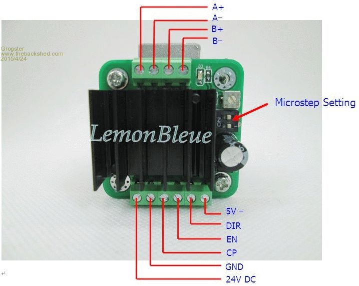
Now, I removed the heatsink mainly so I could see if the driver IC had a marking(it did) so I could research the chip, and what do I find on the silkscreen under the heatsink? (rhetorical) 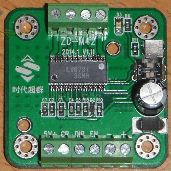
Notice the totally different pinout from the graphic on the eBay listing? I will hook the motor back up to the driver with just the button for a start, and I HOPE it will work. Due to the wrong wiring diagram, this module may be fried, as I have been applying 13.8v to the left-most bottom connection, which is actually the 5v logic supply, so I might have cooked the module cos of their wrong diagram.
The image on the listing is TOTALLY wrong. The PCB silkscreen ID appears to be correct, following the tracks. Stay tuned - I will test this now, and post back with the results - wish me luck! Smoke makes things work. When the smoke gets out, it stops! |
||||
| srnet Senior Member Joined: 08/08/2014 Location: United KingdomPosts: 164 |
I worked on stepper motors back in the early 1980s, using processors like the 8060 and Z80. In them days stepper motors had to be accelerated from rest to running speed in a fairly controlled way, otherwise they just stalled and vibrated, with no rotation. $50SAT is Silent but probably still working. For information on LoRa visit http://www.loratracker.uk/ |
||||
| Grogster Admin Group Joined: 31/12/2012 Location: New ZealandPosts: 9063 |
SUCCESS!!! Funny how when you use the correct wiring, the bloody thing works, for God's sake....
I will email the seller that their diagram is totally wrong. If I follow the silkscreen, I can have full control of the speed of the stepper from zero to full speed. ...unbeleivable.......  Smoke makes things work. When the smoke gets out, it stops! |
||||
| Grogster Admin Group Joined: 31/12/2012 Location: New ZealandPosts: 9063 |
You still seem to be right. I note that if I don't ramp-up and ramp-down the motor PWM for the stepper speed, the motor can and does stall. However, at least the motor is now turning. The controller chip would also seem to not be 5v tolerant. If I run the 5v input at 3v3 the motor turns and the PWM speed control works. If I run the 5v input at 5v, the motor easily stalls. This despite the eBay listing saying the inputs are 5v tolerant, so not sure what the hell is actually going on there - will now look for a datasheet for the chip used on this module - it may give me some more information. Smoke makes things work. When the smoke gets out, it stops! |
||||
| viscomjim Guru Joined: 08/01/2014 Location: United StatesPosts: 925 |
Hi Grogster, glad you got it going. I love using these little units. They work quite well. I am using them with little nema 17 motors with 24vdc and they are great. If you look around on the web, you can find them cheap and also the same units with the parts on the otherside of the board so you can mount a heat sink like these . Have fun, it can get a bit frustrating (stepper motors) but still fun can be had. EDIT... Talk about CHEAP |
||||
| MicroBlocks Guru Joined: 12/05/2012 Location: ThailandPosts: 2209 |
Could it be that 5v has faster rise and fall times that changes the timing a bit? Do you have a scope or logic analyzer to measure the signal at the input pins of the chip.? Microblocks. Build with logic. |
||||
TassyJim Guru Joined: 07/08/2011 Location: AustraliaPosts: 5905 |
The 5V intolerant problem might be because you had hit it with 13.8V. Good that it works and your supplier might send a replacement to fix the 5V problem. Jim VK7JH MMedit MMBasic Help |
||||
| Gizmo Admin Group Joined: 05/06/2004 Location: AustraliaPosts: 5016 |
Yep ramping the speed up and down is important, especially if there is a lot of mass to get moving. Accelerate too quickly, and once you miss a few steps, the motor cant keep up and just makes a horrid buzzing noise. On my CNC table, I played around to get the absolute maximum speeds and acceleration rates, then halved those values to make it reliable and never miss steps. Glad to see you got it sorted. Glenn The best time to plant a tree was twenty years ago, the second best time is right now. JAQ |
||||
| Grogster Admin Group Joined: 31/12/2012 Location: New ZealandPosts: 9063 |
I had a couple of those tiny modules like the ones you linked to, but these ones were a QFN IC type. These units seemed to be very unreliable, and I could not make them behave, so I tried the modules mentioned in this thread, as they use a much larger chip and heatsink for some heat dissipation. Once I figured out the wrong wiring, then the driver seems to work well. I do have another module(I bought two), so I might put the other one in there and see if it behaves with 5v logic. I don't care about running the logic at 3v3, as the MM runs at 3v3 and outputs 3v3 too, so if it works........
I wanted to use a stepper after reading about their fabulous low-speed control and torque. I figured that one of these NEMA-17 things would make the perfect sheave motor for my model elevator project(yes, it is still there in the background of things), and now that I have the motor ramping up and down reliably, it will be PERFECT, as it has such low-speed power. Not that I NEED that much torque really, as the model, even as a model, uses a counter-weight just like the real elevators do, so the main job of the sheave motor is to get things moving, then the system is RELATIVELY balanced be design. In my case, I have set the module to 16th steps, and ramping from 250Hz to 15kHz provides beautifully smooth acceleration and deceleration. I expect I can now put the sheave pulleys directly on the stepper motor. Tests with just me holding the shaft of the stepper in my fingers still allow very nice speed control under quite a lot of load(finger pressure), and the motor does not stall. Starting to see why people like these stepper motors! 
EDIT: OK, I now have full forward and reverse control with slow-down in both directions. The slow-down is used when the controller senses that the elevator cabin within the shaft is at mid-door position relative to the floor it needs to stop at. It slows down to a crawl, then when it detects the cabin is aligned with the floor, stops the sheave motor. This is all proof-of-concept at the moment, and the code just runs in a loop, but it is working beautifully, and the stepper has amazing power even at the very slow speeds. 
MAXSP=5000:MINSP=250:DIR=14:UP=0:DN=1:FWD=1:REV=0:SLOW=MAXSP/2-1500 SetPin DIR,DOUT:Pin(DIR)=FWD Do MOTOR (MINSP,MAXSP,UP,FWD) '(Minimum Speed, Maximum Speed, Module DIR, Forward or Reverse) Pause 2500 MOTOR (SLOW,MAXSP,DN,FWD) Pause 2500 MOTOR (MINSP,SLOW,DN,FWD) MOTORSTOP Pause 2500 MOTOR (MINSP,MAXSP,UP,REV) Pause 2500 MOTOR (SLOW,MAXSP,DN,REV) Pause 2500 MOTOR (MINSP,SLOW,DN,REV) MOTORSTOP Pause 2500 Loop Sub MOTOR (MNSP,MXSP,UD,FR) If UD=0 Then If FR=FWD Then Pin(DIR)=FWD If FR=REV Then Pin(DIR)=REV For x = MNSP To MXSP Step 100 PWM 1,x,50 Pause 25 Next EndIf If UD=1 Then If FR=FWD Then Pin(DIR)=FWD If FR=REV Then Pin(DIR)=REV For x = MXSP To MNSP Step -100 PWM 1,x,50 Pause 25 Next EndIf End Sub Sub MOTORSTOP PWM 1, STOP End Sub End Short 20s video of stepper motor in action. Smoke makes things work. When the smoke gets out, it stops! |
||||
| StoveMan Regular Member Joined: 29/03/2013 Location: United StatesPosts: 51 |
@ Grogster: Could you use the stepper for position control directly? Just count steps between floors and you will know when you are approaching. Of course PWM will not work for this; must use PIN and PAUSE in a loop. Tried just inverting a pin to get more speed but my cheap drivers' optos were to slow. Your driver may well work with this method though as you were pulsing at 15K. Real elevator control is not acceptable with open loop control, so if that is the design intent then you still need floor position feedback to zero your counters. I have used steppers with the Maxi. and speeds of 350 RPM are achievable with acceleration; but the counting loops hog the processor some. |
||||
| Grogster Admin Group Joined: 31/12/2012 Location: New ZealandPosts: 9063 |
An interesting idea, Steve.
Had not thought of that. In my case, I was going to use the I2C bus with a collection of shaft sensors to tell the controller where the cabin is at any point. The problem I was having with this idea, is that as I2C is a master/slave arrangement, slaves can only send data to the master, when the master asks for it. Slaves can be run as master, and the master as a slave, but that is getting too complicated - unless someone wants to open my eyes to how simple it really is
So I am now looking more closely at 485 or even just plain old serial as the run is short, and a nice slow baud rate like 300 or even less. I don't need more then a few bytes at a time. I have to admit to being a little in love with the MM serial port buffers, which automatically take care of any data coming in espically, and you just check if LOC>0 to find out if there is something there for attention. I have used this feature on a couple of my serial projects now, and it is fecking brilliant. 
I guess I should point out if I have not already, this is only for a model. I don't have plans to try to take on Shindler, KONE or Otis!  Smoke makes things work. When the smoke gets out, it stops! |
||||
| MicroBlocks Guru Joined: 12/05/2012 Location: ThailandPosts: 2209 |
A uMite support Slave/Master mode. Can switch between those modes easily according to the manual. Microblocks. Build with logic. |
||||
