
|
|
Forum Index : Microcontroller and PC projects : Bluetooth Madness
| Author | Message | ||||
jman Guru Joined: 12/06/2011 Location: New ZealandPosts: 711 |
Hi All I thought I would share my experience with the cheap Bluetooth modules that are available from our favourite online sellers. Maybe this post will save some other members a little time It also seems to be pot luck as what type you receive I have found 3 different versions all based on the same hardware HC-05 the preferred option HC-06 limited to slave mode only BT04 Different AT command structure so incompatible with HC-05 software See the pic below the one on left is the BT04 (they look exactly the same) After some Google Fu I found a blog about flashing the modules with an SPI interface adapter. Link below Byrons Blog The Requirements are (I used a Windows XP laptop) LPT port SPI programmer as per the schematic below A copy of Bluesuite 2.4 (CSR SDK) this can be downloaded for free at CSR (Free registration required) HC05 firmware from here HC05 firmware Once the software is installed copy the contents for the HC05.Zip to the BlueSuite 2.4 folder and run the following from the command prompt while in the BlueSuite 2.4 directory BlueFlashCmd -DUMP oldfirmware (This saves the current firmware to oldfirmware.xpv) pscli query data.psr data.psq (This saves the modules oscillator calibration) BlueFlashCmd HC05 (Update to HC05 firmware) pscli merge data.psr (Restore calibration data) Done now your module is a HC05 

To make it easier to handle carrier PCB's are been used these provide an easy way to power and connect the modules to your device. One short fall is that the EN pin of the carrier PCB is used to enable the power supply and does not put the module into command mode this is done with a push button on the carrier PCB. To solve this you need to remove a SMD resistor and add a wire link as per the picture below. This now allows the command mode to selected via software and a I/O pin. 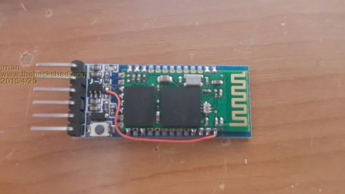
Regards Jman |
||||
BobD Guru Joined: 07/12/2011 Location: AustraliaPosts: 935 |
Jman Thanks for that mod with the wire. I have just bought some HC05s with the push button and your mod may be quite useful. I have just ripped a copy of your post for later reference. Bob |
||||
| BobD Guru Joined: 07/12/2011 Location: AustraliaPosts: 935 |
Jman See the image. Can you be more precise about the resistor to be removed and the location of the wire. I think you are talking about the resistor at the yellow arrow. Where to attach the wire? Bob 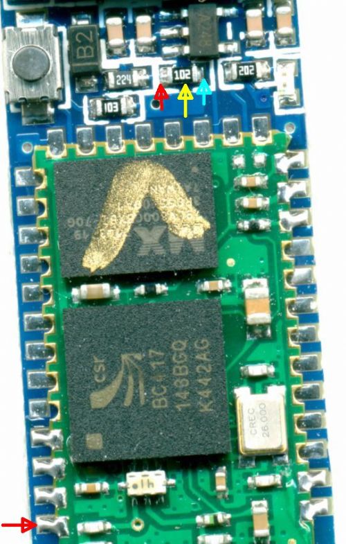
|
||||
Grogster Admin Group Joined: 31/12/2012 Location: New ZealandPosts: 9078 |
Looks to me like in jman's original image, the wire link is soldered to the point marked by the cyan arrow in your image above. I also agree that he is meaning the resistor at the yellow arrow point. Smoke makes things work. When the smoke gets out, it stops! |
||||
| BobD Guru Joined: 07/12/2011 Location: AustraliaPosts: 935 |
Grogs I had an inspiration. I copied the image from the forum. Expanded it to full size of a 24" screen and then snipped a copy and you are correct. See the fuzzy image. Bob 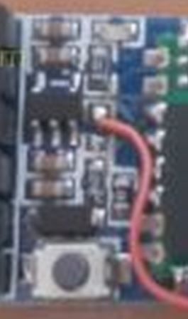
|
||||
| jman Guru Joined: 12/06/2011 Location: New ZealandPosts: 711 |
Correct resistor Yellow wire goes the resistor pad furthest from the button cyan arrow Attached a better pic JG2015-06-14_194513_BTMod.zip Jman |
||||
| BobD Guru Joined: 07/12/2011 Location: AustraliaPosts: 935 |
Jman thanks Bob |
||||
