
|
|
Forum Index : Microcontroller and PC projects : 4.3" Touch-Screen 40 pin FPC socket
| Author | Message | ||||
| paceman Guru Joined: 07/10/2011 Location: AustraliaPosts: 1328 |
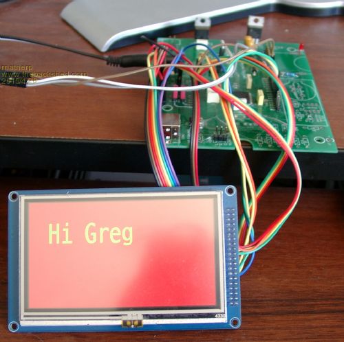
@matherP Peter - what socket/connection are you using to break out the 40 pin FPC connector on the 4.3" screen that you linked to with the MX470 B16 firmware update post today. Greg |
||||
| matherp Guru Joined: 11/12/2012 Location: United KingdomPosts: 8584 |
Do you mean this elegant and sophisticated interconnect 
|
||||
| paceman Guru Joined: 07/10/2011 Location: AustraliaPosts: 1328 |
Truly a thing of beauty Peter - and since you've shown me yours I'll show you mine.  The little board and button is my pinboard transferable PFC8563 RTC with battery backup. The little board and button is my pinboard transferable PFC8563 RTC with battery backup.

I was wondering about the connector to the 40 pin flexible coming out of the screen you linked to though which isn't broken out. The screen in your photo above is already PCB mounted with the flexible broken out (to 0.1" headers??) and I'm wondering how best to connect others that just have the flex connector and no PCB. Some time ago (18 months?) I bought in several different 40 pin, 0.5mm spacing SMD connectors (e.g. Molex 54104-4031, HIROSE FH19SC-40S-0.5SH, Tyco Amphenol part no. 1470360) thinking I'd make a breakout board for the 5" Innolux AT050TN33 TFT touchscreen used for the TFT Maximite. Adafruit have a multi-pitch one here but it's pretty big. On a different subject - is there some fairly minimal (i.e. not the full range) colour pallette Vs hex no. available for the 2.4" screen with the ILI9431S controller? Just for fun I've included some code below showing a simple updating clock on the 2.4" screen. Just demonstrates how simple you've made the graphics. Greg 'Simple Clock
'Firmware - MX470 MMBasic V4.6B++b15 '--------------------------- CPU 96 DIM INTEGER BLUE = &H001F RTC GETTIME DISPLAY OPEN ILI9341S,1,11,3,2,240,320 CLS black ROTATE 3 'landscape, J2 pin1 at top SETTICK 1000,update DO: LOOP SUB update DISPLAY 5,40,40,blue,black,DATE$ DISPLAY 8,0,120,blue,black,MID$(TIME$,1,5),2 END SUB |
||||
Grogster Admin Group Joined: 31/12/2012 Location: New ZealandPosts: 9063 |
Nice to see a few SkinnyMite PCB's showing up in a photo or two.  
I really must make the space to play with the TFT's. I have the 4.3" and the 7" parallel ones here, but never seem to find the time to tinker with them. Smoke makes things work. When the smoke gets out, it stops! |
||||
| paceman Guru Joined: 07/10/2011 Location: AustraliaPosts: 1328 |
You're missing out Grogs! BTW - Did you notice the little 1K resistor in the red wire (console Rx into the MX470), neat eh! BTW2 - that photo setup of mine is using the 2.4" screen of course. Greg |
||||
| matherp Guru Joined: 11/12/2012 Location: United KingdomPosts: 8584 |
On the SSD1963-based displays the controller (i.e.the SSD1963 chip) is on the PCB so without that nothing will work. The PCB also has the touch controller if that is relevant for a particular application. |
||||
| paceman Guru Joined: 07/10/2011 Location: AustraliaPosts: 1328 |
Yes the link you gave this link says that it includes the SSD1963 controller but there is just the flexible 40 pin connector to connect to, not PCB headers - I guess the controller is hidden under the flat back of that screen. How is the connection made though between the flexible connector(s) and the PCB in your photo above that has them broken out to headers? Is the flexible soldered direct to the unseen side of the PCB or does it have a 40 pin socket there to match the 0.5mm spacing flexible lead pins? |
||||
| matherp Guru Joined: 11/12/2012 Location: United KingdomPosts: 8584 |
Sorry about the link - my bad I suspect this display doesn't have the controller - but it is impossible to tell. It certainly doesn't have the boost circuit for the backlight - note it asks for 21V for the backlight. This one has the boost circuit on the flexible PCB so may also have the controller. You could try emailing the vendors but I wouldn't be hopeful of a very useful response I bought this one |
||||
| paceman Guru Joined: 07/10/2011 Location: AustraliaPosts: 1328 |
Ahh.. OK, it makes sense now. The 21v boost circuit was needed for the 5" Innolux AT050TN33 TFT touchscreen used for the TFT Maximite. It was built separately onto the TFT Maximite PCB and a 40 pin SMT socket for the flexible was also mounted on the PCB. The options now like you've mentioned above are a whole lot easier to implement because that 40 pin, 0.5mm connector is tiny - not to mention the software! Greg |
||||
