
|
|
Forum Index : Microcontroller and PC projects : An embarrassing Saga
| Author | Message | ||||
bigmik Guru Joined: 20/06/2011 Location: AustraliaPosts: 2870 |
GDay All, My recent BackPack 170 PCB that I just released has a circuit to drive the back light LED that I found rather difficult to get to function correctly. The specification of the particular modules I use has the LED backlight with a Grounded Cathode and requires 3.2V at 60-80mA to the LED pin on the TFT module (there is a series 3R9 resistor on board the TFT module as well). Now obviously the MicroMite cant directly drive 60-80mA so it requires a transistor to switch the required power from one of the power supplies (5v or 3v3). With approx 1v drop across the C-E junction when the transistor is saturated that means the 5V supply must be used. OK.. Simple enough, I have designed transistor switches many times going back 30+ years.. Visualise bigmik rummaging around for a breadboard and a bunch of resistors and transistors.. I dutifully wire up a standard NPN emitter out to the TFT and collector to 5V and driven from the uMite pin via a 1k resistor, expecting it all to work but NO!!!!! It refused to work as expected.. Scratch my head and think a bit more and realise the problem.. as the Emitter would sit at 3.2V the uMite can only output 3.3V so it cannot turn the transistor ON.. Do a Dr. Google (as we do these days when we are lazy) and a myriad of designs later I still havent got one that works.. Now, by works I mean it MUST be able to turn the TFT OFF fully and also ON fully, I could get dimly on (but not off) or off but not fully on.. I tried PNP circuits and NPN ones but still wasnt happy. It was hair raising.. Eventually I found a PNP circuit that used a diode in series with the uMite pin and that lit the proverbial light above my head. Still there was some issue but it was the best so far.. I then tried it with an NPN with collector to 5V and emitter to the LED and it didnt work.. in the process of swapping transistors around (My selection consisted of BC547, BC557 and BC337), I accidentally inserted my BC337 backwards so that it was as shown in the following image (which is the way that BackPack 170 is currently. It was `almost' perfect! After a couple of resistor value changes I got it working really well.. 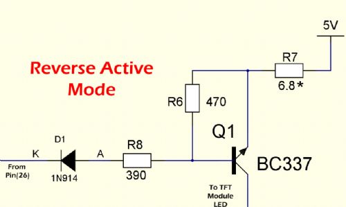
But Hey!! That transistor is BACKWARDs.. Thats not right.. But it works!! Hmmm what to do? So back to Dr. Google for reverse connected transistors and lo and behold it is not an uncommon design practice, there are heaps of references including this one from `Sparkfun' (search for Reverse Active).. So I released the board as it was, half comfortable with it.. Sparkfun Now Cliff, from the back shed forum, questioned this and was not convinced as to its suitability.. This made the purist in me revisit the design, so I bread-boarded it again.. Proved that the REVERSE ACTIVE worked and worked well but this time I reversed the transistor into a more traditional layout and bugger me.. IT WORKED.. I have since built a BP170 with the transistor reversed (well in actuality NOT-Reversed) and can confirm it does indeed work. Hmm, why didnt this work the first time I tried it?? I can only assume it had something to do with the breadboard design and some component not connecting to the holes in the breadboard correctly.. (I usually use solder proto boards but this time used those solder-less ones. I remember Phil's warnings about these a month or so back.. I can now concur with his sentiments. What does all this mean? Well it means that transistor, as shown, is actually backwards but does work and is unlikely to be damaged due to the low 5V max supply, and does seem to be a (at least semi) legitimate design. I will alter the manual to suggest mounting the transistor 180 degrees to get it to work in standard configuration. The new circuit would now look like this. 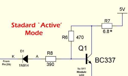
Oh well it shows sometimes you can be too smart for your own good. Kind Regards, (an embarrassed) Mick  Mick's uMite Stuff can be found >>> HERE (Kindly hosted by Dontronics) <<< |
||||
Grogster Admin Group Joined: 31/12/2012 Location: New ZealandPosts: 9063 |
Interesting - never thought of putting an NPN transistor around that way before! 
My new friend these days is the MOSFET - what with it's practically zero-ohm S-D on resistance - perfect for switching, and much less lossy then a bi-polar, although I still have a soft-spot for the 548/558 and 337's...  Smoke makes things work. When the smoke gets out, it stops! |
||||
| JohnS Guru Joined: 18/11/2011 Location: United KingdomPosts: 3659 |
Out of curiosity... what would the circuit be like using a MOSFET (if anyone has the inclination & time to show it)? John |
||||
| matherp Guru Joined: 11/12/2012 Location: United KingdomPosts: 8584 |
It is worth measuring the current going into the LED pin on any specific display before getting too clever with this. On some displays (e.g. the SSD1963 mounted boards) the LED pin is a logic signal that switches a circuit that actually drives the display. It draws almost no current. It is perfectly OK with this display to connect "LED" directly to a PWM pin on the Micromite and use this to set the backlight. In fact the SSD1963 controller has its own PWM output which is optionally selectable on the SSD1963 PCB. 
The initialisation code for the SSD1963 in the ARMmite and the MX470 turns on this PWM and sets it to a level that on my display gave optimum brightness for minimum duty cycle. At some stage I'll write some code to expose this facility as a user function. |
||||
| robert.rozee Guru Joined: 31/12/2012 Location: New ZealandPosts: 2289 |
Mick: i'm a little confused by by your explanation. am i right in saying you were at first attempting to use an NPN transistor with collector to 5v, and load strung between emitter and ground? this will definitely NOT work, as the emitter can never rise above (Vbase - 0.6) volts - ie, you'll get approximately 2.7v (or a bit less) across the LEDs if the base is driven by a micromite output pin that can go no higher than 3.3v. this will light your LEDs dimly (as you have observed). furthermore, with correctly driven base and less than 100mA collector current, i would expect the Vce of a BC547 to be quite low, according to one datasheet: with Ic=100mA and Ib=5mA, Vce(sat)=250mV typical. from where i am, it seems you should be using your "reverse active mode" circuit with a PNP transistor in place of the BC337, emitter to 5v, R7 bridged, R8 about 1k5. if pin 26 is set to 'open collector' output, then D1 will probably not be needed. when used as switches, it is safest to use an NPN transistor to switch the low side, or use a PNP transistor to switch the high side. if Vload is higher than Vmicro, then use 2 transistors when switching the high side - a PNP transistor to switch the load, and an NPN transistor to switch the base drive to the PNP one. and remember - the base voltage of a bipolar transistor is quite entitled to be higher than the collector voltage; whereas valves (and FETs) are voltage-mode devices, bipolar transistors are current-mode. cheers, rob :-) |
||||
| JohnS Guru Joined: 18/11/2011 Location: United KingdomPosts: 3659 |
Rob, Thanks. (Except the "and remember" as I was out of my comfort zone by then!) John |
||||
| hitsware Guru Joined: 23/11/2012 Location: United StatesPosts: 535 |
Like this ..... |
||||
| JohnS Guru Joined: 18/11/2011 Location: United KingdomPosts: 3659 |
D'oh! I didn't realise it'd be so simple. John |
||||
| bigmik Guru Joined: 20/06/2011 Location: AustraliaPosts: 2870 |
Hi Robert, Yes, As I said that was my first attempt.. but as I have mentioned and you have stated that does not work.. Ideally it would have been so easy if the LED was illuminated by Grounding the Cathode but the design of the panel was to supply 3.2V to the ANODE.. I also tried the PNP using a BC557 but I also couldn't get exactly the swings that I wanted.. As to open collector, Maybe but then I dont think PWM can be open collector. Also pin(26) is not 5V tolerant. The difficulty is that the output required (3.2V) is so close to the uMites maximum output of 3.3V that it is difficult to turn on the transistor. Whilst a Motfet may be good here it also `may' not work.. I would like to see it performing first.. It is possible.. In reality I agree a 2 transistor circuit would have been better but I didnt have the room for 2 transistors and all the bias resistors unless I went SMD which I tried to avoid. I have these neat little SMD chips (3mm x 2mm that have the follwing footprint but these would have made the board difficult to solder for many people. 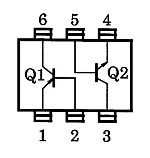
The bottom line is it works, and works well for the TFT back light drive. and the logic of the output is TRUE ... 0=OFF and 1=ON. I am more than happy to see someone build it using the mosfet.. This is the reason for the post, to get ideas and make us think. I am not really familiar with mosfets., What part would you recommend and I am happy to try it out. Regards, Mick Mick's uMite Stuff can be found >>> HERE (Kindly hosted by Dontronics) <<< |
||||
| Grogster Admin Group Joined: 31/12/2012 Location: New ZealandPosts: 9063 |
Mick - I had the same exact issue when needing to switch 3v3 to a data transmitter module, from the Micromite also running on the same common 3v3 supply. A transistor such as a 337, even as an emitter-follower with the RF module in the collector circuit, is going to lose at least 0.6v across the transistor. With higher voltage headway, this does not matter, but as the voltage drops, the sensitivity to voltage-drop becomes more important, as I am sure you already know. Have a look at this thread for details and help from others in deciding on a MOSFET to do the job, and the final device works beautifully, driven from the MM, to switch the high-side of the RF module, keeping the RF module's common-ground. Your post was still very interesting, Mick - thanks for posting.  Smoke makes things work. When the smoke gets out, it stops! |
||||
centrex Guru Joined: 13/11/2011 Location: AustraliaPosts: 320 |
One thing to remember the tft modules Mick's board is designed for runs at 3.3volts.Mick's revised circuit while switching the 5volt railensures that only 3.2 volts ends up on the led pin. I have it running just a single led with no problems as a test. 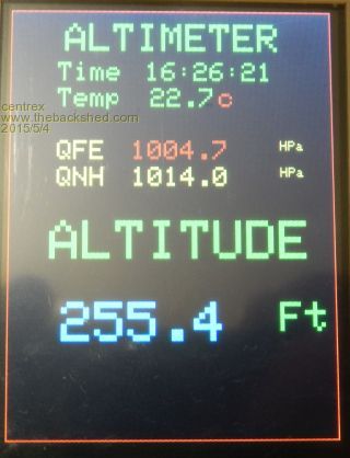
Bigmicks driver board matherp software driver BMP80 pressure sensor, my altitude a bit south west of Sydney. Regards Cliff Cliff |
||||
