
|
|
Forum Index : Microcontroller and PC projects : Micromite module troubles
| Page 1 of 2 |
|||||
| Author | Message | ||||
| CarlRanson Newbie Joined: 08/05/2015 Location: New ZealandPosts: 30 |
Hi all, I've been trying to build up some 44-Pin micromite modules as discussed in the Aug 2014 Silicon Chip. I should note that this is my first extensive attempt at surface mount soldering. Now the first one I built up did nothing at power-up. After measuring voltages I found the that voltage after the PTC was only 1.6 or so. I did have some trouble with the PTC during soldering so I reasoned I had damaged it and just bridged it (stop laughing). This didn't fix the problem, so I decided to build up the second module minus the two IC's. I figured this would give me a chance to measure all the voltages we're correct. To my surprise, this one ALSO came out with 1.6v after the PTC. I've checked all the soldering and it all looks ok. Good joins etc. Any ideas what i've done wrong, what to check? thanks for your help, CR |
||||
| WhiteWizzard Guru Joined: 05/04/2013 Location: United KingdomPosts: 2794 |
Ok - think I should step in here! Please check/answer the following: 1> Can you remove the 2-pin jumper (near the USB socket) and measure the voltage coming into the module from your power source 2> Are all components mounted or are some 'left out' for now (other than the 2 ICs you mention) 3> Can you submit a close-up photo of the 'completed' unit with the 'bridge' in place of the PTC Will walk you through things if you stay online . . . WW For everything Micromite visit micromite.org Direct Email: whitewizzard@micromite.o |
||||
| WhiteWizzard Guru Joined: 05/04/2013 Location: United KingdomPosts: 2794 |
Q4> Can you check all connections on the USB socket. The fact you are getting 1.6V is a figure that can derive from 5v in less 3v3 required . . . . Waiting for feedback from you before next suggestions  For everything Micromite visit micromite.org Direct Email: whitewizzard@micromite.o |
||||
bigmik Guru Joined: 20/06/2011 Location: AustraliaPosts: 2870 |
Gday Carl, Phil, Is the micromite in Aug SC mag one of yours Phil? If so I will leave this up to your capable hands.. But first.. Phil, I think you may have hit the nail on the head about 1.6V. That sounds suspiciously like Carl may be measuring between 5V and 3v3 instead of GND and 3v3. Carl, If you send a picture of your soldered board can you point out what two points you put your meter on to measure the 1.6V? Also where did you get your PIC32 chip from? It needs to be flashed with MMBasic before it will do anything.. You need a PicKit3 or similar programmer to do this. Regards, Mick Mick's uMite Stuff can be found >>> HERE (Kindly hosted by Dontronics) <<< |
||||
| CarlRanson Newbie Joined: 08/05/2015 Location: New ZealandPosts: 30 |
The voltage at one side of the PTC is 5v as expected from the USB. The second module (with the same problem) has all the components installed *except* both IC's, Led1 & 2 and their resistors, the pin headers & reset switch and the 47uf that would connect to pin 7 of IC1. No bridges on the usb connection. This one HAS the PTC installed. The first one is where I bridged it. Thanks, Carl |
||||
| CarlRanson Newbie Joined: 08/05/2015 Location: New ZealandPosts: 30 |
Oh, and measuring from Pin 6 (gnd) against the 3 pins at the end, I get 1.62 on the 5v, 1.44 on the 3.3v and 0 on the gnd. I do get 5.09 at the jumper which is directly off the USB socket. |
||||
| WhiteWizzard Guru Joined: 05/04/2013 Location: United KingdomPosts: 2794 |
Yep - Geoff wrote that article based on my module. Please do chip in though (two heads better than one etc) EDIT - OR did you mean is his module from me or SC? For everything Micromite visit micromite.org Direct Email: whitewizzard@micromite.o |
||||
| WhiteWizzard Guru Joined: 05/04/2013 Location: United KingdomPosts: 2794 |
Carl, The voltage readings you provided above are from which module - the 'populated' one or the 'part-populated' one? What regulator are you using? Are you using a 'compatible' one that has a different pinout? The fact you are getting 5v in but something totally incorrect out implies an issue around the vReg. We will need photos before we can suggest much more . . . . For everything Micromite visit micromite.org Direct Email: whitewizzard@micromite.o |
||||
| WhiteWizzard Guru Joined: 05/04/2013 Location: United KingdomPosts: 2794 |
ONE MORE TEST: Can you remove the jumper on the two pin header from the 'populated' module. Then use a meter to measure the current flowing in the 5v line (i.e. across the 2-pin jumper). Thanks For everything Micromite visit micromite.org Direct Email: whitewizzard@micromite.o |
||||
| bigmik Guru Joined: 20/06/2011 Location: AustraliaPosts: 2870 |
Hi Phil, As I no longer subscribe to SC I had no idea what module it was.. I will absorb what Carl has posted before I comment further. To date I have only used the 28pin micromites so I need to work out what pins do what.. Mick Mick's uMite Stuff can be found >>> HERE (Kindly hosted by Dontronics) <<< |
||||
| CarlRanson Newbie Joined: 08/05/2015 Location: New ZealandPosts: 30 |
The voltages are from the part-populated one. here's a photo. 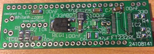
Yes, C7 is pretty crappy but I swear it looks ok under magnification. The regulator has the markings LF33 GKLFB323. It looks damaged on the left side but that is just flux. looks ok now i've wiped it. and yes, I've put a bridge wire in, instead of the normal jumper at this point. I just twigged that you're *that* WhiteWizzard. thanks for your help. |
||||
| WhiteWizzard Guru Joined: 05/04/2013 Location: United KingdomPosts: 2794 |
First observation is that the47uF cap across the vReg is the wrong way round (or at least I believe it is). On SMD caps, it is normally the +ve side that is marked (in this case with the white line). This is the opposite method of 'assumed' marking to through-hole caps where the -ve lead is marked. Anyway, that said it shouldn't make a difference but is worth trying briefly . . . Let me look more at the photo and get back to you with anything else (Yep I'm WW) For everything Micromite visit micromite.org Direct Email: whitewizzard@micromite.o |
||||
| WhiteWizzard Guru Joined: 05/04/2013 Location: United KingdomPosts: 2794 |
If you are mid way through turning the cap around then please LEAVE THE CAP OFF first and quickly measure the voltage on the 3v3 output again (this eliminates any soldering issue around this cap (providing you clean the SMD solder pads first)) TWO MORE OBSERVATIONS/POINTS: 1> Have you got a good solder connection on the vReg on the 'big' GND pin on the left hand side (and not just on the two pins on the right hand side). Your photo shows it is soldered but it needs to be a good join (as this is GND for the whole circuit). 2> Is there anything in the PTC space? It looks like there is solder there but no component - I know you have made reference to the PTCs on both modules - I just need to be clear on what you have on the module in the photo. If you have a high-res (i.e. larger) photo then please feel free to email me - it will give me a better view than possibly the posted photo (phil.boyce@micromite.org) WW For everything Micromite visit micromite.org Direct Email: whitewizzard@micromite.o |
||||
| CarlRanson Newbie Joined: 08/05/2015 Location: New ZealandPosts: 30 |
OMG, who came up with that scheme.... and BINGO, that was the problem exactly. |
||||
| bigmik Guru Joined: 20/06/2011 Location: AustraliaPosts: 2870 |
Hi Carl, I think that there is a 3v3 Regulator on the underside of the PCB, What part Number is it? I think by looking at the track layout it should be MCP1825S or MCP1826S... If you put an LM1117 instead the pinout is different.. Regards, Mick Mick's uMite Stuff can be found >>> HERE (Kindly hosted by Dontronics) <<< |
||||
| CarlRanson Newbie Joined: 08/05/2015 Location: New ZealandPosts: 30 |
yes, the ptc is installed on that photo (its green on green). Yes, pretty sure there is a great join on the regulator, I tinned the big pad first so it should be a big thermal join right, going to go swap the two caps on the first module and see if it works thanks for your help |
||||
Grogster Admin Group Joined: 31/12/2012 Location: New ZealandPosts: 9063 |
If it makes you feel any better Carl, I had the EXACT same issue as you with SMD tant caps when I first ran into them. So much so, that for a time, I vowed to never use SMD tants again, as they were so weird with their polarity markings compared to more standard caps. I now have all my SMD in seperate little compartments, and caps are marked on the lid - BAR POSITIVE kind of thing. It's an easy mistake to make, and you are lucky that the board obviously likes you - tant's, like most polarised caps, don't like being connected with reverse polarity. A blown tant is like a mini-volcano, and not good to be close to! 
Glad you got it sorted, and welcome to the forums, BTW.  Smoke makes things work. When the smoke gets out, it stops! |
||||
| bigmik Guru Joined: 20/06/2011 Location: AustraliaPosts: 2870 |
Yes, That Cap IS backwards.. I was writing when the picture of your board came in.. If you zip the photo and upload it it we can then get a better quality picture of your board. It looks like you have the correct VReg installed but I cant quite read the number on it. I cannot see anything else of concern.. Mick Mick's uMite Stuff can be found >>> HERE (Kindly hosted by Dontronics) <<< |
||||
| CarlRanson Newbie Joined: 08/05/2015 Location: New ZealandPosts: 30 |
right, the first module (with the ics installed) is now presenting the correct voltages. It registers as a usb device to the pc and then appears as an unknown Tomorrow problem...time for beer and GTA. As for making mistakes, I already managed to burn a hole through my minimite when using it to try out some i2c displays (mixed 5v and 3.3v supplies). And I cooked the first of my esp8266 modules as well. If you're not letting the smoke out sometimes, you're not really learning. thanks again all for the help. CR |
||||
| bigmik Guru Joined: 20/06/2011 Location: AustraliaPosts: 2870 |
Good news Carl, Enjoy stealing cars and running over innocent children.. 
Regards, Mick Mick's uMite Stuff can be found >>> HERE (Kindly hosted by Dontronics) <<< |
||||
| Page 1 of 2 |
|||||
