
|
|
Forum Index : Microcontroller and PC projects : Car Steering Wheel Interface
| Author | Message | ||||
jman Guru Joined: 12/06/2011 Location: New ZealandPosts: 711 |
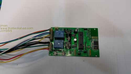
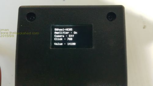
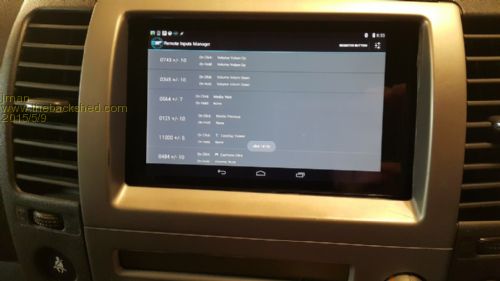
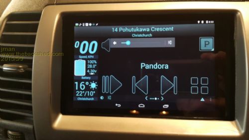
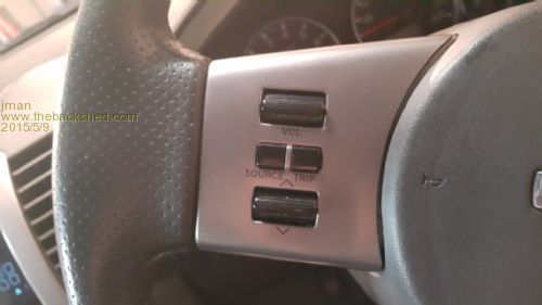
Hi I thought I would share my latest project. Micromite MKII HC05 Bluetooth Car Interface I have Nexus 7" Tablet in my car hence the project This device is a Bluetooth car interface for a Android Phone / Tablet It sends a code via Bluetooth and this is used by an Android application to make the phone or tablet perform various functions It has the following functions. 12v Relay output to Amplifier remote delayed to avoid thump on power up 12v Relay output for reverse camera Analogue Steering wheel interface (Buttons press to code via A/D) Reverse camera control via +12v trigger from reverse light Rotary encoder for Volume control Press Button (Incorporated into rotary encoder) Short Press (Programmable in android Application) Long Press (Programmable in android Application) +8 second press will restart Bluetooth connection. Input from Car Phone Kit This will mute the Amplifier and pause the current media (My Car phone audio is routed to the front right speaker by the car kit) 1st Dash mounted press button Press to turn on reverse camera (Even if car is not in reverse) Press again to turn off reverse camera 2nd dash mounted press button Press sends a code Release sends a code Each function sends a different number to the Android application Steering Wheel Buttons (Depends on resistor values in car) Phone triggered 10000 Phone call complete 10100 Reverse +12 input 11000 Reverse complete 11100 Dash Switch #1 1st press 12000 Dash Switch #1 2nd press 12100 Dash Switch #2 press 15000 Dash Switch #2 release 15100 Rotary Encoder right 14000 Rotary encoder left 14100 Rotary Encoder switch Long Press < 1 second 13100 Short Press > 1 second 13000 Long + Press > 8 seconds reinitialise Bluetooth Then just because I had a .96" OLED display I added that so you can see the codes sent when setting it up in the car (Thanks to Peter for code) The PCB was kindly designed by Grogster (Many Thanks G). The code,PCB's and Android Application are available should anybody be interested. Please note the idea and the Android code are from _cre_ on the XDA forums Link to original posting. -link- Better quality pictures are here Pic1 Pic2 Pic3 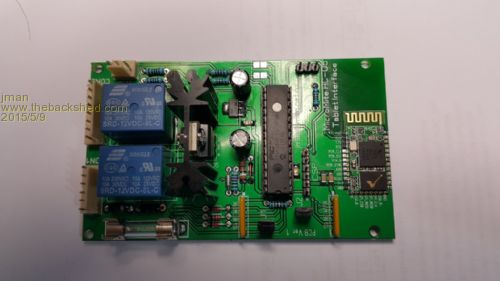
And in action 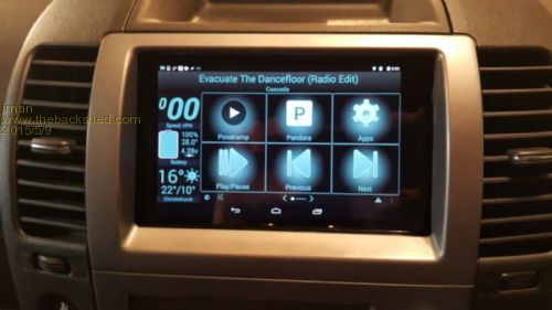
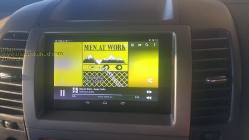
Rename the below to *.apk (this is the Android application) 2015-05-09_033215_RemoteInputsMgr-1.3.2.zip Micromite MKII MMBasic code (1st Version so probably with bugs :) ) 2015-05-09_033425_PathFinder-OLED.zip Apologies for the long winded post but hopefully somebody finds it interesting Regards Jman |
||||
| Gizmo Admin Group Joined: 05/06/2004 Location: AustraliaPosts: 5016 |
The ingenuity and quality of some of the projects posted here never cease to amaze me. Nice work Jman. The best time to plant a tree was twenty years ago, the second best time is right now. JAQ |
||||
| viscomjim Guru Joined: 08/01/2014 Location: United StatesPosts: 925 |
Hi Jman, first of all, GREAT project. I am flipping through your code and it is very interesting as always. I have a quick question as to your style as I am always trying to learn to code better. In your mainloop, you do... for instance If Pin(HFree)= 0 Then GoSub Mute then you define mute as Mute: code code code return Is this any different than if you did... If Pin(HFree)= 0 Then Mute and define mute as Sub Mute code code code end sub When would you choose one over the other? Also, could you explain how the SetPin 2, INTB, ReadAD works? ie what causes the interrupt and when it happens, what is the source of the analog value that you are reading? Thanks for your input and again, great fn project! |
||||
| jman Guru Joined: 12/06/2011 Location: New ZealandPosts: 711 |
Thank you for looking through the code. I am sure there are better ways to do it than the way I do it. I use this style as it what I am used to and it makes easy reading (for me anyway) As to your question nope no difference both methods will work some people don't like the use of goto and gosub's in their code and the use of SUB's is a way to overcome this. I grew up in the dark ages so goto's and gosubs are fine by me :) SetPin 2, INTB, ReadAD This will set pin 2 as an any change interrupt. (As you already know) The source is the Steering Wheel buttons So if a button on the steering wheel is pressed the SUB ReadAD is run and then we use SetPin 2, ADIN to set the pin to read the analogue value once we have read the analogue value we run SetPin 2,INTB, ReadAD again. The steering wheel buttons have quite low value resistors going to ground hence the ADVal * 100 we now have a value for each button. Hope that helps Jman |
||||
| viscomjim Guru Joined: 08/01/2014 Location: United StatesPosts: 925 |
Thanks for the reply! In your ReadAD routine, you are setting the ADRead pin (pin 2) to an analog input and in the same routine you are doing SetPin 2, INTB, ReadAD. I guess that is confusing me as I thought that SetPin2, INTB, ReadAD makes the pin a digital input to trigger an interrupt. Maybe it would be clearer to me if I knew what the resistor circuit looked like. Does the SetPin2, INTB, ReadAD also work with a change in analog voltage? Also in the same routine you have... Do While Pin(ADRead) < 3.0 Loop So I am assuming the circuit attached to pin 2 will provide a voltage greater than 3v? Sorry for all the questions. I am just curious now. Thanks Again! |
||||
| jman Guru Joined: 12/06/2011 Location: New ZealandPosts: 711 |
Hi Yip correct I am using the analogue voltage as the source of the interrupt as this goes low enough to be seen a digital low input. Do While Pin(ADRead) < 3.0 Loop Correct this checks if the voltage is greater than 3v as this indicate that the steering wheel button has been released. Not shown on the circuit diagram is a 10K pull-up resistor to 3.3v So when the steering wheel buttons are open circuit the value of the AD will over 3 volts 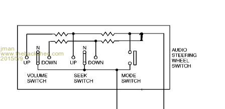
Hope that helps Jman |
||||
OA47 Guru Joined: 11/04/2012 Location: AustraliaPosts: 902 |
Jman, very professional project I congratulate you. I noticed that the PIC is socketed, do you think that reliability of the unit will be hampered? GM |
||||
| jman Guru Joined: 12/06/2011 Location: New ZealandPosts: 711 |
Thank you for the kind words. I did think about that but decided to fit it and see what happens :) I suppose a little hot glue would not hurt. Jman |
||||
| aargee Senior Member Joined: 21/08/2008 Location: AustraliaPosts: 255 |
Well done!! I built a small interface for my car to my after-market Pioneer radio that overcomes a few issues that drove me bonkers. 1. My car is a button start, when you turn the engine off the electrics just die, unlike a key type ignition where it goes back to the "Accessory" position and the stereo keeps running. My box detects the main 12V going off and holds the Acc voltage to the stereo on for 5 seconds. If the start button is subsequently pressed to enable Acc then it stays on, otherwise it just goes off as normal after the 5 seconds. Now I can keep listening to the radio, MP3, etc uninterrupted. 2 If running with headlights on during the day, the screen auto dims. I have an LDR and an override switch. If lights are on and it is bright in the cabin, no dimming. The switch manually does the same thing. OEM automotive entertainment design leaves a lot to be desired. My design uses a Picaxe 14M but I've been tempted to port it over to one of Micks little Micromites in the 8pin form factor. But alas - Time and tide wait for no man. For crying out loud, all I wanted to do was flash this blasted LED. |
||||
| paceman Guru Joined: 07/10/2011 Location: AustraliaPosts: 1328 |
A really nice job John - I'm not sure I've got what you're doing quite straight though. Have you installed a Nexus 7 into the dash or was it already there? I guess this is running the Android app and that sends the bluetooth commands to the uMite which then does all the other I/O control - or have I got this back-to-front? Was the analogue signal from the steering wheel already there or did you modify it all? I'm amazed you've kept it all so neat Greg |
||||
| viscomjim Guru Joined: 08/01/2014 Location: United StatesPosts: 925 |
Thanks again for the reply! One more question (hopefully). I come to understand that using a ucontroller in a automotive environment has its challenges as to the power supply. Have you found anything unusual about making things work in a car? Did you have to do anything different with the power supply ciruit you are using? |
||||
| jman Guru Joined: 12/06/2011 Location: New ZealandPosts: 711 |
@ Greg Thank you for the comment The car originally had a 6 CD in Dash Player. I removed it and installed the Nexus in it's place. (Thank goodness for my 3D printer). The Umite sends the data TO the tablet and the Android app process's it and preforms the relevant command. The only mod I did to the Steering Wheel controls was to add a series resistor. @ Viscomjim The PCB as a ground Plane pour. The PSU is just a LM7805 and LM1117-N for the 3.3V. The board has lot of decoupling caps and the regulators have the required caps. Polarity protection is provided by a 1N4007 in series with the 12v input Hope that helps Jman |
||||
disco4now Guru Joined: 18/12/2014 Location: AustraliaPosts: 844 |
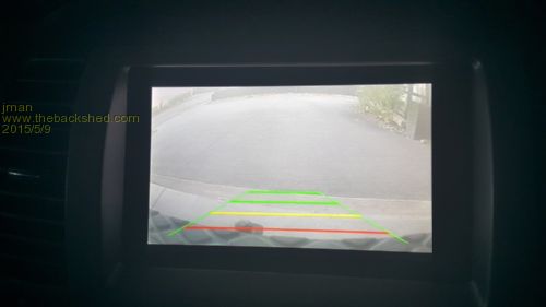
Hi Jman, Neat project. I am interested in how the rear vision camera video is interfaced/works with the Nexus as a display. Regards Gerry Latest F4 Latest H7 |
||||
| jman Guru Joined: 12/06/2011 Location: New ZealandPosts: 711 |
@ Gerry This is done using a USB video grabber the Android Kernel I am using has the driver included. The USB grabber was sourced from here USB Video Grabber And lastly I use an Application called EsayCap that can be obtained from the Play Store here EasyCap Hope that helps Jman |
||||
