
|
|
Forum Index : Microcontroller and PC projects : Micromite eXtreme: Navigation focused PCB
| Author | Message | ||||
| matherp Guru Joined: 11/12/2012 Location: United KingdomPosts: 8597 |
 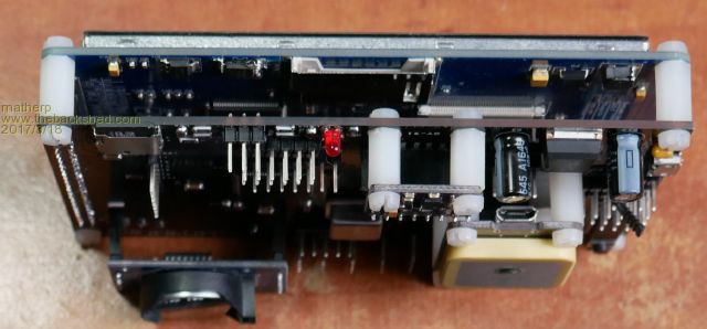 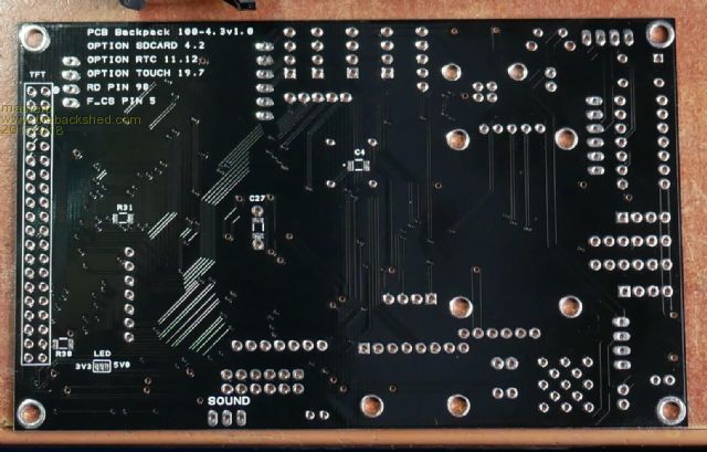 Here is a new PCB for the 100-pin Micromite eXtreme. This is sized to mount the 4.3" SSD1963 display and has mounting for a GPS A 10-DOF AHRS And if required a RTC module All the pins are broken out somewhere on the board and as usual it uses a PIC16F1454 as a USB/UART and onboard PIC32 programmer Here is the full schematic 2017-03-18_163345_Schematic.pdf If anyone wants the gerbers let me know. If you want a built version you need to twist one of the usual suspects' arms. |
||||
| Bill7300 Senior Member Joined: 05/08/2014 Location: AustraliaPosts: 158 |
Very neat, Peter. You never cease to amaze me. I would certainly like the gerbers, or to get a pcb if any of the normal suspects is thinking of stocking these. Bill |
||||
| matherp Guru Joined: 11/12/2012 Location: United KingdomPosts: 8597 |
2017-03-19_091141_Backpack100min.zip |
||||
| cdeagle Senior Member Joined: 22/06/2014 Location: United StatesPosts: 261 |
Nice looking board Peter. I would like to see the eXtreme at the core of a programmable calculator. Along with a 7" display and numeric keypad.  |
||||
| panky Guru Joined: 02/10/2012 Location: AustraliaPosts: 1098 |
WW, Are you going to supply bare boards or made up systems? If bare boards, I will certainly take 2 please. Cheers, Doug. ... almost all of the Maximites, the MicromMites, the MM Extremes, the ArmMites, the PicoMite and loving it! |
||||
| WhiteWizzard Guru Joined: 05/04/2013 Location: United KingdomPosts: 2794 |
Yes I certainly will as I think there will be some interest in these too. I am only just catching up with Peter's MMX64 2.8" BackPack but will order some of these PCBs this week from PCB fabricator. For everything Micromite visit micromite.org Direct Email: whitewizzard@micromite.o |
||||
palcal Guru Joined: 12/10/2011 Location: AustraliaPosts: 1805 |
@ WW Have you got any of these boards yet, no hurry but I would like one if and when available. Paul. "It is better to be ignorant and ask a stupid question than to be plain Stupid and not ask at all" |
||||
| palcal Guru Joined: 12/10/2011 Location: AustraliaPosts: 1805 |
@ Matherp On the Schematic there are 2 pull up resistors on the I2C Bus. R21 and R22 but I can't find them on the PCB. Are they not needed. There are 2 resistors in the sound output not marked but I can probably work them out. Also can't find R33 on the schematic. Paul. "It is better to be ignorant and ask a stupid question than to be plain Stupid and not ask at all" |
||||
| matherp Guru Joined: 11/12/2012 Location: United KingdomPosts: 8597 |
Hi Paul R21 and R22 are the pullups on the I2C2 bus - they were missed off this version of the board - sorry R33 is the left resistor in the audio right channel, same as r28 for the left channel, R35 is the centre resistor in the audio right channel, same as R34 for the left. |
||||
| CaptainBoing Guru Joined: 07/09/2016 Location: United KingdomPosts: 1986 |
Hello Peter. How often does the board need calibrating for the AHRS? Is it once, once in a while or each time? cheers |
||||
drkl Senior Member Joined: 18/10/2015 Location: HungaryPosts: 102 |
Hello Peter, What is the role of the MODE part in the schematic? It seems as a microbridge+programmer isn't it? cheers |
||||
| matherp Guru Joined: 11/12/2012 Location: United KingdomPosts: 8597 |
It is just the momentary switch that sets the mode on the microbridge - just a silly schematic I used as it had the correct footprint Should only be once as long as the items within say 15cm of the PCB/sensor remain the same |
||||
