
|
|
Forum Index : Microcontroller and PC projects : pin soldering problem
| Page 1 of 2 |
|||||
| Author | Message | ||||
| klsmurf Newbie Joined: 31/03/2017 Location: United StatesPosts: 8 |
Hi all, Newbie here. I have one of Grogster's E-28 modules and have soldered the header pins on. Never done this before, but it seemed to go well and all looked good. I tested the pins and found a couple that didn't work. I re-melted the solder, but that didn't help. I'm looking for suggestions and mind you I have no special tools. This is just a hobby/learning tool, so if I loose a couple of pins, no big deal. One of the pins however, is pin 3 and this is SPI out on this board. I have a small touch screen I was going to connect. Am I now SOL or is there a work around. Thanks Kevin |
||||
| WhiteWizzard Guru Joined: 05/04/2013 Location: United KingdomPosts: 2794 |
Hi Kevin, and welcome onboard  There are a couple of versions of the E28 - any chance you can take a quick picture of your module (nothing fancy!). If it is the newer version (it has a larger SOIC version of the PIC rather than a small square QFN PIC) then is it possible for you to also just run your iron over the PIC pins. Occasionally these may get missed during manufacture (rarely - but possible). By the way - 'SOL' ? Sorry - trying to work it out  WW For everything Micromite visit micromite.org Direct Email: whitewizzard@micromite.o |
||||
| klsmurf Newbie Joined: 31/03/2017 Location: United StatesPosts: 8 |
Hi WW It's a QFN chip and they all look to be soldered. By the way, I have no clue how you guys solder those chips. SOL= sorry-outta-luck *appropriate slang can be used instead of sorry |
||||
| WhiteWizzard Guru Joined: 05/04/2013 Location: United KingdomPosts: 2794 |
Ok - thanks for confirming that it is the QFN type! These PICs are MUCH harder to solder by hand so there may well be an issue with an open circuit on pin 3. However, what makes you say pin 3 is not working? Are you plugging the E28 module into a breadboard and then driving something like an LED which is then not coming ON when expected? IF so - then it could be that the breadboard is faulty! Try moving your circuit along a few pins within the breadboard and see if pin 3 is still a problem OR whether now another pin on the E28 (the same number of 'holes' along) becomes the 'new problem pin'. IF so, then this implies a Breadboard issue (contact strips within cheap bread-boards can sit too low, or even be missing, resulting in 'open circuit issues'). NOTE: don't move E28 up/down the same contact strips, move it 'sideways' to 'new' strips! Hope this makes sense  Likewise - swap jumper cables around too to eliminate any faulty ones. IF the issue remains with pin 3 then I can only suggest you run a 'dry' soldering iron quickly across the pins of the QFN. ONLY do this if you are feeling confident! Another method is a heat-gun (or hot hair dryer) if you have one available WW For everything Micromite visit micromite.org Direct Email: whitewizzard@micromite.o |
||||
| klsmurf Newbie Joined: 31/03/2017 Location: United StatesPosts: 8 |
I had thought it might be the breadboard, so I checked it before posting. I've checked jumper wire to top of pin to led. I've checked with my DVM and no voltage when pin was high. At this time, I am not confident with messing with the chip itself. I've got a heat gun somewhere I may try, but I suspect my solder job is the culprit. |
||||
Grogster Admin Group Joined: 31/12/2012 Location: New ZealandPosts: 9066 |
Hi and welcome.  I am sorry you are having an issue with the E28.  ALL the E28's we have sent out are checked on a special jig that cycles through all the I/O pins to confirm they are all working, so what I can tell you, is that pin-3 would have passed on the test-jig before your module was sent to you - any failure would instantly fail that module, and it would then be fixed, or put to one side and another one that DID pass the test would have been sent instead. Something to try: Start up the E28 and connect to it. At the console: > setpin 3,dout > pin(3)=1 Now measure the voltage ACROSS PIN-3 AND GROUND. Totally remove anything you might have already connected to pin-3, and just put your meter across pin-3 of the module and ground. You should get a reading of about 3.3v If you don't, something is indeed wrong. Smoke makes things work. When the smoke gets out, it stops! |
||||
| klsmurf Newbie Joined: 31/03/2017 Location: United StatesPosts: 8 |
Hi Grogster, |
||||
| klsmurf Newbie Joined: 31/03/2017 Location: United StatesPosts: 8 |
So, from this point, I'll assume I can't use this pin unless I can correct my solder job. The second question was, since this is designated as "SPI out" am I correct in assuming I can't connect my touch screen TFT now? |
||||
| WhiteWizzard Guru Joined: 05/04/2013 Location: United KingdomPosts: 2794 |
Kevin, Using your DVM, can you confirm continuity between E28 Pin 3 (that you have soldered) and QFN corner pin that the track leads to (i.e. the QFN pin near the letters 'er' in the silkscreen word 'Version1A'. You may need to use a component lead off-cut to poke the QFN pin with (most DVM leads will be too thick to get onto the QFN pad). If no continuity then it may be fixable. AFAIK, the SPI pin is required for the TFT  There maybe some fancy C-Function that allows definable pins - but I don't recollect there being one. There maybe some fancy C-Function that allows definable pins - but I don't recollect there being one.Lets live in hope you can locate the issue with pin 3. Could you post a close-up photo by any chance? WW For everything Micromite visit micromite.org Direct Email: whitewizzard@micromite.o |
||||
| isochronic Guru Joined: 21/01/2012 Location: AustraliaPosts: 689 |
Didn't see anything about that ... Any more info there ? |
||||
| klsmurf Newbie Joined: 31/03/2017 Location: United StatesPosts: 8 |
You just want to see my solder job.  Sorry, my phone camera is not up to it. Cheep flip phone. I checked between the chip pin and the header pin and got a reading, so I powered up the module. set the pin high and viola! 3.302V I guess I hadn't done enough probing earlier. Thank you both for your suggestions. There's a short somewhere. I'll keep at it. What setting and how close for the hair-dryer? Kevin |
||||
TassyJim Guru Joined: 07/08/2011 Location: AustraliaPosts: 5915 |
pin 3 is also analog in so you can test for open circuit by SETPIN 3, AIN do print pin(3) pause 10 loop If there is a short to ground, the result will be very close to zero. If the pin is floating, the result will wander about a bit. If it is wandering, try shorting the external pin to ground and if the result is still wandering, there is an open circuit between the external pin and the chip pin. You can also try shorting the external pin to 3.3V You can also try tapping the chip around the suspect pin while the program is running to see if there is a bad joint that momentarily comes good. Jim edit: You can also look for a hairline crack in a trace by running a pin along the trace. VK7JH MMedit MMBasic Help |
||||
| Grogster Admin Group Joined: 31/12/2012 Location: New ZealandPosts: 9066 |
That's cos we've not published it yet. Well spotted.  Yes, there is a new version that uses the SOIC 170 chip instead of the QFN, making assembly much easier. Exactly the same size as the QFN version. Tidyed up component placement on the bottom layer. Still has the 1455 USB chip on the bottom layer, also still SOIC. Me or Rob will start a new thread soon - we are still building the prototypes. 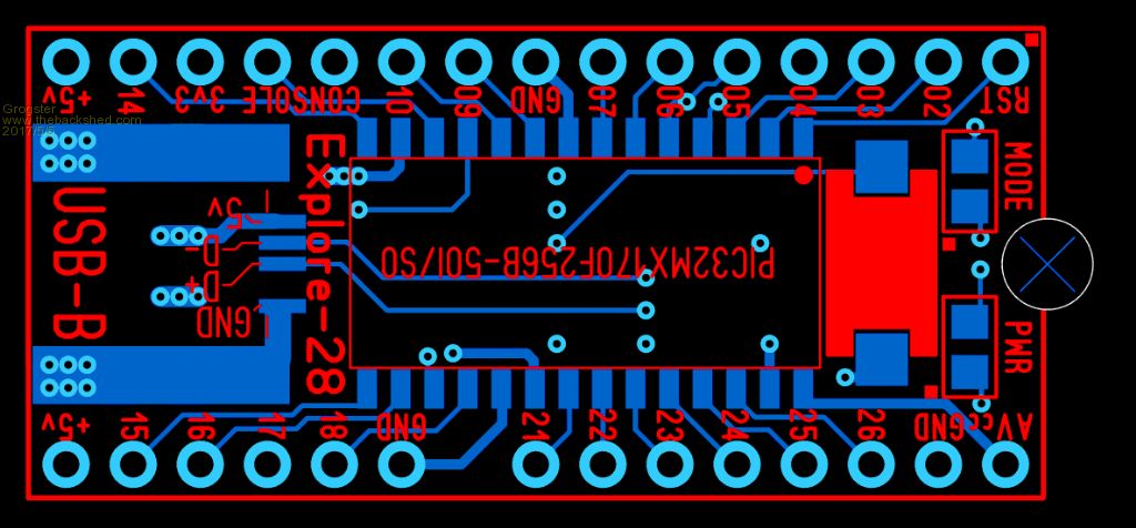 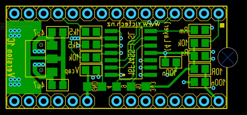 Smoke makes things work. When the smoke gets out, it stops! |
||||
jman Guru Joined: 12/06/2011 Location: New ZealandPosts: 711 |
But I want one now :) Jman |
||||
| lizby Guru Joined: 17/05/2016 Location: United StatesPosts: 3019 |
+1 And a SOIC Explore-44.  Lance Oops--44-pin apparently not available in SOIC. PicoMite, Armmite F4, SensorKits, MMBasic Hardware, Games, etc. on fruitoftheshed |
||||
| Grogster Admin Group Joined: 31/12/2012 Location: New ZealandPosts: 9066 |
@ jman - well, if you eat up all your dinner..... The QFN was actually not really that difficult to hand-solder, but it took much longer to align and check the pins then the SOIC due to it's very small size. The original revised concept was to use the SSOP chip, then Rob(or WW - he's also been helping behind the scenes) suggested SOIC. I was extremely doubtful that you could ever fit the larger SOIC 170 in there keeping the PCB the same size, but in the actual event, it proved to not be that much of a problem, so WW or Rob - whichever one of those chaps that suggested using the SOIC - were right all along. I think the 1C is a very efficient PCB layout now. 1B was the SSOP version, but was aborted.All the 1A's produced thus far have been fine(except for perhaps the thread-starter's one?), it was just a design change to make for easier assembly, and a neater layout of the passives on the bottom layer. Smoke makes things work. When the smoke gets out, it stops! |
||||
| WhiteWizzard Guru Joined: 05/04/2013 Location: United KingdomPosts: 2794 |
I have built a couple of the new E28s, and they are currently under stress testing here. Confirming that, as expected, this module is so much easier to assemble than the QFN version. They layout was 'fine tuned' over many emails and I think that Grogs has done a great job on the PCB to fit Rob's circuit within the size it is. Will be adding the SOIC Explore28 onto micromite.org very soon (for people this side of the planet wanting to get their hands on one)WW For everything Micromite visit micromite.org Direct Email: whitewizzard@micromite.o |
||||
| WhiteWizzard Guru Joined: 05/04/2013 Location: United KingdomPosts: 2794 |
Now added onto website (link here)Anyone in New Zealand or Australia wanting one of these excellent modules should contact Grogster/Rob as shipping will obviously be quicker and cheaper!  For everything Micromite visit micromite.org Direct Email: whitewizzard@micromite.o |
||||
| Andrew_G Guru Joined: 18/10/2016 Location: AustraliaPosts: 842 |
Hi, I've only just "discovered" Explore 28 (not enough exploring on my part?) and I too am keen to get my hands on several when they become available (I have, until now, been using an LCD Backpack or Veroboard to make up my own circuit with a DIL 170, capacitors, resistors etc.). Please bear with me but it helps me if I re-state what I have just read. Using the schematic for an Explore 28 Mark 1A am I right in thinking, in the terms of a 170 DIL: - pins 1, 8, 11-13, 19 and 27-28 are reserved? - the other pins are "available" but with the capabilities described in Geoffg's documents? - pins 1, 15-18 and 18-19 are 5V tolerant? - the power supply can be EITHER via the USB (5V) OR up to 16V via a "5v0" pin (ie after 14 or before 15) and pin 19, 8 or 27 for the ground? I too am so grateful that you guys have put in the effort to design, assemble and distribute them at such a reasonable price (please don't move to China . . .), Cheers, Andrew |
||||
| WhiteWizzard Guru Joined: 05/04/2013 Location: United KingdomPosts: 2794 |
When you state 'in terms of a 170 DIL' then I assume you mean a 28pin PIC32MX170 chip. If so then your answers are as follows: Almost: 1,8,13,19,20,27,28 are not usable as they are power related pins. Pins 11 & 12 are usual but 99% of the time they are used for the 'console' connection (Rx & Tx) Correct NO 5v tolerant I/O pins are: 14, 15-18,21,22 ?? This makes me think you mean the pinout for the Explore28 Module ?? The PIC chip requires between 2.6v and 3.6v. Typically 3v3 is used as many other peripherals also require 3v3, The Explore28 module has a 3v3 vReg onboard which drops down a 5v input (from a 5v pin OR the 5v pin on the USB socket). I would avoid going much higher than 5v as vRegs can get warm/hot. The max inout is dependant upon which vReg is used. My rule is to simply stick to 5v as there are many 5v PSUs out there used for things such as Raspberry Pis or mobile Phones. NOTE: The Explore28 is a 30pin module (actually 29 pins!) which is why I think your '170 DIL' pin references in your question relate to a 28pin PIC chip Hope this has helped WW For everything Micromite visit micromite.org Direct Email: whitewizzard@micromite.o |
||||
| Page 1 of 2 |
|||||
