
|
|
Forum Index : Microcontroller and PC projects : 3v input problem....
| Author | Message | ||||
| Phil23 Guru Joined: 27/03/2016 Location: AustraliaPosts: 1664 |
So what's the disadvantage of doing the hardware solution like Geoff uses in most of his GPS projects? It was what I had in mind for all my HC-12's, which I'd rather run on 5V, so there's less load on the 3.3V supply. 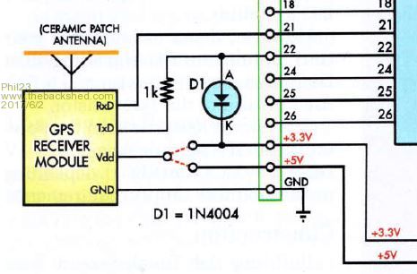 Phil. |
||||
| JohnS Guru Joined: 18/11/2011 Location: United KingdomPosts: 3678 |
Do you mean to have GPS Vdd at 5V? What is the max voltage drop A-K when TxD is high i.e. what is the max volts on pin 22? (And is it within PIC32 spec?) I take it that the 1k is intended to provide a current limit? But as there are apparently no clamping diodes in the PIC32 is the 1k guaranteed to work? John |
||||
| WhiteWizzard Guru Joined: 05/04/2013 Location: United KingdomPosts: 2794 |
Perhaps I've missed something - but why not remove this pull-up on the Dout, and then simply add your own to 3v3. Then can feed into MM input. For everything Micromite visit micromite.org Direct Email: whitewizzard@micromite.o |
||||
| piclover Senior Member Joined: 14/06/2015 Location: FrancePosts: 134 |
@Phil23 In your schematic, the 1N4004 diode (200V/1A rectifier diode) is an overkill, and being a Silicium diode, it will only clamp at 0.7V or so above Vdd, which is beyond specifications for a PIC 3.3V inputs. I use small BAT85 Schottky diodes for such a clamping (will clamp at around 0.3V above Vdd, i.e. within specs). |
||||
