
|
|
Forum Index : Windmills : Windmill DIY Analog MPPT Circuit
| Author | Message | ||||
| RetepV Newbie Joined: 17/10/2014 Location: NetherlandsPosts: 4 |
Hi, I took the liberty of cleaning up the schematics somewhat. I hope it's useful. 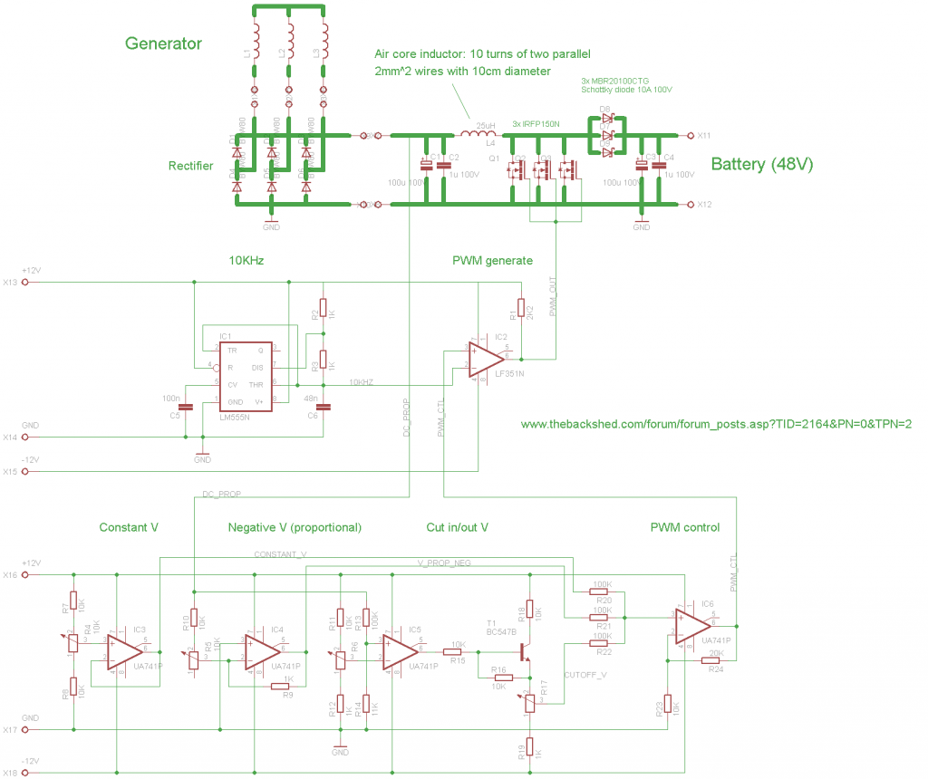
Edit: Ah, I didn't know it would be resized. Give me some time and I will post a higher resolution image via photobucket or something. |
||||
| Gizmo Admin Group Joined: 05/06/2004 Location: AustraliaPosts: 5012 |
If you save and upload as GIF, the forum will resize to 1000 pixels wide instead of 500, as it does for JPG's GIF's are perfect for circuit diagrams, cad drawings, etc, and are resized to 1000 pixels wide. JPG's are more suitable for photos, and are resized to 500 pixels wide. Glenn The best time to plant a tree was twenty years ago, the second best time is right now. JAQ |
||||
| jm1010 Newbie Joined: 15/03/2019 Location: FrancePosts: 1 |
Hello, It has been a long time since nobody talked on this topic but I'll try to ask my question anyway. I am very interested in this setup but I would like to connect it to a grid-tie inverter instead of a battery. In particular, I have an Enphase M250 (solar micro inverter) that I would like to use on my DIY Wind turbine. I would like to directly convert the energy towards the grid using the micro-inverter, without using a battery. As I understand the circuit, the battery is useful in order to provide a reference voltage that is used by the control circuit to generate the correct PWM duty cycle to the boost inverter and thus the optimal DC voltage to the windmill for optimal power production. Would this circuit still work by connecting an inverter at the output instead of a battery? The M250 inverter has a DC in voltage range from 16V to 48V, but unlike a battery it does not provide a constant reference voltage at its input. Instead, it varies the voltage in order to find the MPP. I already tried connecting my generator directly to the micro inverter input using only a rectifier in between, this works but the micro inverter places itself at its minimum voltage point (16V) and draws the available current. However, it is not guaranteed that it will remain at 16V for higher currents for example. Indeed, I could only produce 2-3A from the generator by turning it by hand, just for testing, because my windmill is not ready yet. I will use a hubmotor from an electric bike, so I could already test the behavior by connecting the motor output to the inverter and pedaling manually on the bike to generate electricity. Maybe an additional circuit would be required between the ouput of the circuit presented here and the micro inverter ? At some point in the discussion it was said that people who would need to reach a higher DC voltage at the generator than at the battery could use an additional buck converter... Maybe adding such a converter could work, by providing a constant voltage to the inverter but preventing it from varying the voltage at the output of the circuit ? Thank you very much for your help! |
||||
