|
|
Forum Index : Windmills : Guy anchor block
| Author | Message | ||||
| brucedownunder2 Guru Joined: 14/09/2005 Location: AustraliaPosts: 1548 |
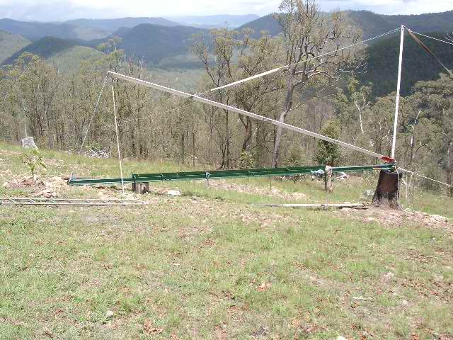
This one is tricky(for me). The base block and attachment steelwork is fitted for my mast. the land is sloping quite a bit , forward and aft guy anchor points are not a problem. Now ,the big question is , how do I calculate accurately the side "point-of-attachment" length from the centre ,say 30 feet out from centre ?. The high side is no problem as the ground is level at this point-just drive a peg in at 30 feet. The other side of ground falls away --is there a easy way to accurately measure and peg the point -of -attachment for this side ? any takers? Thanks Bruce
Bushboy |
||||
| MrBungle Newbie Joined: 07/10/2005 Location: AustraliaPosts: 34 |
Hiya Bruce, just been looking at yer photo's, some nice gear there, wish I had lathes etc. Trigonometry? I'm, having trouble visualising your problem, but I'm thinking it's something like this?:  Sorry if I'm way off! Simo. Edit: eep!, just had a thought, is it 4 wire or 3 wire? If its 3 wire, is the high side a single axis, so the other two are downhill? hmmm tricky. I'm gonna have to blow the dust off my old high-school math books! I can visualise this as a solid form, as a cone with it's base cut at an angle. Similarly, if a guy wire were spun 360deg around the mast, maintaining its angle with respect to the mast, and you traced its path on the ground, you would have an elipse drawn on the ground, the minor axis of the elipse would be 60feet. The major axis = ?(depends on angle of ground) Then the tie down points could be found by faning out at 120deg angles. (or 90 deg for 4 wire) Am I completely off the track? |
||||
| MrBungle Newbie Joined: 07/10/2005 Location: AustraliaPosts: 34 |
Haha, Okay, I've realised I was half way-off, the high side is level, so its a semi circle on the level, and half elipse on the slope! And I'm thinking its got 4 wires, the two side wires are at 30 feet and the high side ground is level, so that one is 30 feet out also. So three of four wires are known, but the fourth, downhill one, needs to be worked out, like in the sketch above, but ignoring the high side? I'm thinking that if the angle of the wire with respect to the mast is known, and the mast height is known, and the angle of the slope is measured, then some trigonometry should get a result, either telling us the length of the wire, or the length of the ground axis. But, being a scalene triangle, could present problems.... A scalene can be broken into two right-angle triangles, which might help some. Oh why didn't I pay more attention in math class! |
||||
| MrBungle Newbie Joined: 07/10/2005 Location: AustraliaPosts: 34 |
Yeehaw, trig isn't as hard as I remember it!, theres a massive amount of info on the net. If my understanding of your problem is correct, then I've found a nice little way to work out the ground length, thats if the mast/wire angle is known, and the mast/ground angle is known, and the mast hight is known. It's simple ratio's:  The mentioned table is here: http://www.themathpage.com/aTrig/trigonometric-table.htm So, for this example, if the 766 is the mast and the 423 is the ground, then the ground length is 423/766 = 55.2% of the mast height. Nice. to quote the website: 'The sides of a triangle are to one another in the same ratio as the sines of their opposite angles' - the Sine Law apparently! Ok, hope that helps, sorry for the multiple posts, and all the thinking out-aloud! Simo Edit: stupid link wouldnt link! Gonna try metatags. |
||||
| brucedownunder2 Guru Joined: 14/09/2005 Location: AustraliaPosts: 1548 |
Thanks Simo--- just knew there was a bright a#rse out there--hahaha. sort of all came back to me when that ratio thingo was mentioned -- Now, to clarify, the back and front guys -forget them,as they are the raising/lowering guys.dosen't matter what length they are. Now, the side guys(2 of them) they have to be equal length so as when the mast goes up and down there is equal strain on these 2 guys ,keeping the mast perpendictular and safe in it's decent. Thats where your stuff comes in -- we know the height,say 25feet, we know the distance out from the mast we would like ,say 25 feet. Now ,what we have to determine is a distance out from the mast base along the raising or sloping ground !. on raising ground it would be less than 25 feet and more than 25 feet on falling away ground.
Thanks , Dumb bruce Bushboy |
||||
| brucedownunder2 Guru Joined: 14/09/2005 Location: AustraliaPosts: 1548 |
Hey Simo -come back , I need you !!!
I hope you didn't take offence at my "smart a#rse" comment --it was meant to be a compliment, thank you . just the way we are here in Oz. great site this ,congratulations to Glenn.
Bruce Bushboy |
||||
| MrBungle Newbie Joined: 07/10/2005 Location: AustraliaPosts: 34 |
Hiya Bruce, sorry about my disappearing, I limit myself to one or two days of internet use every week or so. It's so easy to get addicted to the internet, so I have to minimise my exposure. There are a couple of years of my past I would like back! Don't worry about smart a**e comments, I got me some tuff skin .... *sniff* lol Anyway, we need to know the angle of the ground. The only way I can think of doung this easily, is with a large homemade protractor(just a large bit of card with angles marked on it) and a spirit level. Rest one end of the spirit level on the ground, get it set level, then set the protractor on the ground, with its origin of angle at the same point as the spirit level's contact with the ground...... ahhh... yeah. Here's a bl**dy sketch, never was very good at explainin':  Ooooh, colour! So anyway, hope that makes sense. I'm starting to worry about how accurate this will be. We will only get out what we put in, so we need a fairly accurate angle. And it assumes the mast is dead verticle.... hmmm We'll give it a try anyway eh?. Will try and check back tomorrow. Simo. |
||||
| Gizmo Admin Group Joined: 05/06/2004 Location: AustraliaPosts: 5017 |
Love the flower, thats a real artistic touch there Simo
The best time to plant a tree was twenty years ago, the second best time is right now. JAQ |
||||
| MrBungle Newbie Joined: 07/10/2005 Location: AustraliaPosts: 34 |
LOL! thanks Glenn! |
||||
| brucedownunder2 Guru Joined: 14/09/2005 Location: AustraliaPosts: 1548 |
Thanks Simo. I've just about got it figured out --give or take a couple of inches- I've installed the front and rear blocks and will raise the mast on these with temp. side guys--from here I'll work out the close -as-can position . look in my album and you'll see the progress.
Thanks Bruce Bushboy |
||||
| MrBungle Newbie Joined: 07/10/2005 Location: AustraliaPosts: 34 |
Couple of inches eh? I honestly don't think you could have bettered that using trig and a homemade protractor, so ... same. Edit: Oh hey, I just had a very delayed idea, what if the two steadying wires are on the level ground, and the lift/drop wires are on the slope? Their tie-down/pulley points don't have to be as perfectly positioned right? Too late now I spose. |
||||