
|
|
Forum Index : Windmills : Alston Windmill
| Author | Message | ||||
| joe&janet Newbie Joined: 26/01/2015 Location: AustraliaPosts: 4 |
Hi all. I have just completed restoring an Alston Windmill but have been having difficulties finding a picture or description of the Control Lever. It was not connected when I found the windmill so I am unsure EXACTLY how it is connected. Joe |
||||
| Gizmo Admin Group Joined: 05/06/2004 Location: AustraliaPosts: 5012 |
Where about are you Joe, and what model / year is the windmill? Glenn The best time to plant a tree was twenty years ago, the second best time is right now. JAQ |
||||
| joe&janet Newbie Joined: 26/01/2015 Location: AustraliaPosts: 4 |
Hey Glen, It's an Alston 33/40 20ft. Guess year early 30s. I'm in Somerville on the Mornington Peninsula. Joe |
||||
yahoo2 Guru Joined: 05/04/2011 Location: AustraliaPosts: 1166 |
when you say control lever are you meaning the lever/handle for the cable tail furling system attached to the tower at ground level or something on the head? I'm confused, no wait... maybe I'm not... |
||||
| joe&janet Newbie Joined: 26/01/2015 Location: AustraliaPosts: 4 |
Yes, the tail furling system. I have the chain but I believe that a swivel or as I think it is called 'bracket for tail pipe stay' is missing. The Needle rod goes up and attaches to the chain (internally?). I am inclined to 'jerry rig' a swivel at the bottom near the controller however as the only drawing I have shows the chain attached to the bracket it appears to go up top. There's no space except internally maybe. This is my dilemma. I want to keep it as was designed but can't find a working mill the same nor any drawings to follow. I hope you can follow me. Joe |
||||
| VK4AYQ Guru Joined: 02/12/2009 Location: AustraliaPosts: 2539 |
http://members.iinet.net.au/~caladenia@westnet.com.au/windmi llman.html http://enviroed4all.com.au/wp-content/uploads/2013/06/Alston -gearless-windmill.pdf May be of some use Bob Foolin Around |
||||
fillm Guru Joined: 10/02/2007 Location: AustraliaPosts: 730 |
Hi Bob , That is a great resource the members of the "Morawa District Historical society" have put together there, it is mind blowing that there were that many manufacturers of wind mills and machinery back in the day. My hat is definitely off to the people who would have tirelessly assembled all the manuals and then converted them to CD format for preservation. Here is and unbroken click link http://members.iinet.net.au/~caladenia@westnet.com.au/windmi llman.html I can only imagine 1% of how many good manuals have been burnt and tossed into dumps along with new parts that younger generations would not have a clue what they are looking at. Thanks Bob and good luck with your restoration Joe. You will want everything perfect with the furling if you are running it on the Mornington Peninsula , I was there a few years back and the trees grow low and sideways PhillM ...Oz Wind Engineering..Wind Turbine Kits 500W - 5000W ~ F&P Dual Kits ~ GOE222Blades- Voltage Control Parts ------- Tower kits |
||||
| yahoo2 Guru Joined: 05/04/2011 Location: AustraliaPosts: 1166 |
From what I remember,they are all a similar design. I think the pump rod is angle iron and the needle rod fits inside the angle, the bottom of the pump rod has a hole in it where it is coupled to the guide rods (the needle comes down through this hole in the pump rod and coupler) there should be a casting (bolted to the tower) that loosely holds the two guide bars and the needle rod in the middle this is the point that a cable down to the counter-weighted lever at the bottom of the mill is attached. there should be a bar fitted to back or under the sump there is a sheave/pulley sitting over the pump shaft hole and another that lays flat towards the end of the bar close to the front buffer spring. The furling chain runs around these and clamps to the tail boom pipe. I found a small photo of a 33 that shows the basic idea at the top. beyond the pulley laying flat at the left side of the photo is where the front buffer spring fits. 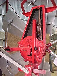
I will have a sniff around I might find a parts picture of the guide bars and coupler setup, it might help you see how it works. I'm confused, no wait... maybe I'm not... |
||||
| joe&janet Newbie Joined: 26/01/2015 Location: AustraliaPosts: 4 |
Thanx guys. The 'Morowa District Historical Society' was my first port of call in aquiring info and I bought their CD on Alston Mills and hard copied a large part of it. Was a great source of info, however it doesn't help with this particular problem. I have a rig set up now that seems to work after having spoken to a fine gentleman plumber whom I located in Shepparton and had himself worked on an Alston in the past. Amazing how many people are more than happy to chat and try to help. Humbling. I would have like to keep it ORIGINAL though and would still like a picture of or sketch of how this was set up maybe to change in the future. Joe |
||||
| yahoo2 Guru Joined: 05/04/2011 Location: AustraliaPosts: 1166 |
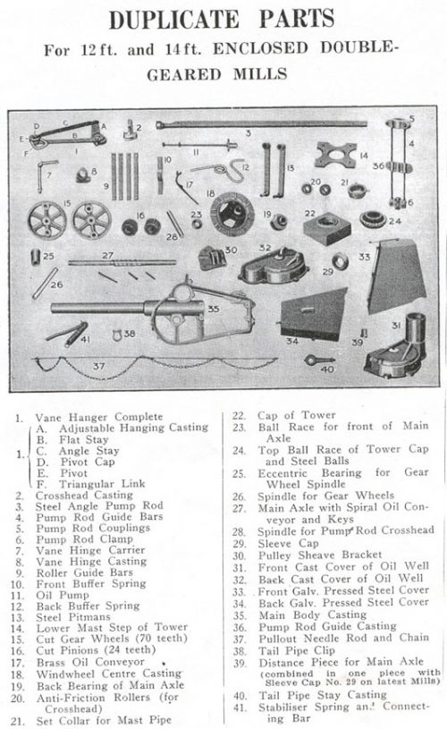
Have you got the bits numbered 4,5,6 and 36 ? (top left corner) the length of the guide rods change with the stroke and amount of furling needed the left end of the pump rod (No 3) fits into the coupler (No 5). No 36 is the bit that is fixed to the tower the needle (37) pokes out of the pump rod (no 3) and down into the guide rod casting (no 36) I'm confused, no wait... maybe I'm not... |
||||
| outback Newbie Joined: 10/02/2018 Location: AustraliaPosts: 1 |
I know I'm digging up an old thread, but as I'm a newbie I reckon I get one free hit. I'm working to restore a 33-40, all is going well except the oil pump. It is rusted, seized and not at all well. I'm not sure how it worked, I guess the two tubes, larger fixed and smaller one running inside and actuated by the pitman had a valve each of some sort to create the pumping action. I suspect these are long gone. As the mill will be put back into work when I'm finished all I need is a replacement or effective method of oiling the top of the pitman and associated linkage. Any insight is greatly appreciated. |
||||
